
Friday, 25 November 2011


Cowling design - Part 2
From my previous post about the cowling you may have got the impression that I was only concerned with the inlets, as that was all I mentioned.
However the inlet to outlet ratio is crucial to get right and there is much that can be done with the outlet to improve cooling performance and efficiency.
Very few aircraft make use of the exhaust gases. If anything they tend to exit at a fairly steep angle to the airstream and make no use of the small amount of thrust that they could provide but more importantly the exhaust gases can be used to accelerate the outlet air speed.
Cooling drag typically accounts for up to 37% of total drag so it is well worthwhile to try to reduce this while still maintaining good temperatures on the engine.
Most outlet cooling drag is caused by the outlet air having to accelerate back up to the free airstream speed and this costs energy and adds drag. By utilising the exhaust gases to accelerate this air we can make them less wasteful and improve overall performance. This is called exhaust augmentation.
Two aircraft that have done this very successfully are the Arnold AR6 (Multiple winner at Reno) and Dave Anders much modified RV-4.
Pictures of both are below.
Dave Anders makes the most of smoothing the air before it gets to the outlet with a simple duct. Piper also did this with the Comanche.
If you want to see a really smooth cooling air outlet - take a look at the radiator exit air duct on a P-51 Mustang - that is very smooth and narrows down at the exit to accelerate the airflow. Of course the P-51 was made famous as the first aircraft to achieve Zero cooling drag. (a function of the thrust that was made with the warm compressed air leaving the exit duct.) It still impresses me.
The AR6 averages more than 220kts (while turning the course at Reno) on 100hp. Look at the bump under the fuselage - that is the cowling air exit and exhaust exit all in one. It worked so well when first made that the owner had to reduce the size of the already tiny inlets to get the temps up!
It is amazing that most aircraft designers pay so much attention to smooth airflow on the outside of the aircraft but almost never pay attention to smooth airflow under the cowl.
On the Twister it will be a challenge to include these design features as space is very limited under the cowl - it was originally designed around a compact Rotary engine - and has changed over the years as various powerplants have been installed. The biggest of these is the UL260. However I believe I can still employ the Lo Presti style inlets and UL power offer a carbon plenum with round inlets as an option which will make the job somewhat easier to implement. I would still like to explore different exit ducts to improve that area as best I can in the space.
However the inlet to outlet ratio is crucial to get right and there is much that can be done with the outlet to improve cooling performance and efficiency.
Very few aircraft make use of the exhaust gases. If anything they tend to exit at a fairly steep angle to the airstream and make no use of the small amount of thrust that they could provide but more importantly the exhaust gases can be used to accelerate the outlet air speed.
Cooling drag typically accounts for up to 37% of total drag so it is well worthwhile to try to reduce this while still maintaining good temperatures on the engine.
Most outlet cooling drag is caused by the outlet air having to accelerate back up to the free airstream speed and this costs energy and adds drag. By utilising the exhaust gases to accelerate this air we can make them less wasteful and improve overall performance. This is called exhaust augmentation.
Two aircraft that have done this very successfully are the Arnold AR6 (Multiple winner at Reno) and Dave Anders much modified RV-4.
Pictures of both are below.
Dave Anders makes the most of smoothing the air before it gets to the outlet with a simple duct. Piper also did this with the Comanche.
If you want to see a really smooth cooling air outlet - take a look at the radiator exit air duct on a P-51 Mustang - that is very smooth and narrows down at the exit to accelerate the airflow. Of course the P-51 was made famous as the first aircraft to achieve Zero cooling drag. (a function of the thrust that was made with the warm compressed air leaving the exit duct.) It still impresses me.
The AR6 averages more than 220kts (while turning the course at Reno) on 100hp. Look at the bump under the fuselage - that is the cowling air exit and exhaust exit all in one. It worked so well when first made that the owner had to reduce the size of the already tiny inlets to get the temps up!
It is amazing that most aircraft designers pay so much attention to smooth airflow on the outside of the aircraft but almost never pay attention to smooth airflow under the cowl.
On the Twister it will be a challenge to include these design features as space is very limited under the cowl - it was originally designed around a compact Rotary engine - and has changed over the years as various powerplants have been installed. The biggest of these is the UL260. However I believe I can still employ the Lo Presti style inlets and UL power offer a carbon plenum with round inlets as an option which will make the job somewhat easier to implement. I would still like to explore different exit ducts to improve that area as best I can in the space.
 |
| Dave Anders RV-4 exit with exhaust augmentation |
 |
| Note aluminum sheet exit duct to smooth airflow |
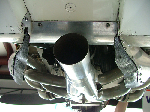 |
| No muffler though so it must be noisy... |
 |
| Arnold AR6 - bump underneath is cowl and exhaust exit |
 |
| The small but perfectly formed Arnold AR6 |
Thursday, 24 November 2011
Week 14 - Aileron hinge pin bearings, reinforcing ailerons
Total hours to date 149.0
Got both aileron hinge pin bearings bonded into the wing, plus reinforcing of the ailerons in the horn and counterweight areas.
Both fuel tanks are now bonded in and I am preparing the parts that will be fitted to them.
The fuel caps come in a lovely anodised red which must be taken off completely where they will be bonded with flock to the wing and tank. Let the Dremel be your friend here! Finish with a corse grade sandpaper to give it a good key. This will be crucial to have fuel tight tanks when done. The black tape in the photos is just to protect the anodised surface that remains after sanding.
Going to buy some hole saws this weekend so may start the cutting of holes for the fuel caps and drains if I'm in the mood.
Got both aileron hinge pin bearings bonded into the wing, plus reinforcing of the ailerons in the horn and counterweight areas.
Both fuel tanks are now bonded in and I am preparing the parts that will be fitted to them.
The fuel caps come in a lovely anodised red which must be taken off completely where they will be bonded with flock to the wing and tank. Let the Dremel be your friend here! Finish with a corse grade sandpaper to give it a good key. This will be crucial to have fuel tight tanks when done. The black tape in the photos is just to protect the anodised surface that remains after sanding.
Going to buy some hole saws this weekend so may start the cutting of holes for the fuel caps and drains if I'm in the mood.
 |
| Ailerons held in place while 5min epoxy sets hinge pin bearings in place. |
 |
| Aileron horn and counterweight reinforcement with 25mm tape |
 |
| Fuel caps |
 |
| One 'virgin' cap and one keyed up |
 |
| Black tape is to protect the inner which keeps its anodised finish |
Thursday, 17 November 2011
Week 13 - Fuel tank fitting
Total hours to date 130.75
Well I took the plunge and bonded in one of the tanks last night.
The job seemed to go okay.
First off I sanded down the raised solder blobs so that the tank would be as flush as possible with the inner of the wing. This should maximise the bonding surface.
Then I did a 'dry run' - installing the tank without the PU foam on it to make sure it would slide in easy and not catch on anything - just as well I did, there was a little tweaking required to make it fit easily. Actually I found once it was covered in the PU foam it slid in easier. But you don't want to find something catching when the tank is covered in PU - best to find out these things in advance.
I also did a test piece first to get a feel of the working time of the PU foam - all the info on the pack is in German and Russian so that wasn't much help. The photo below was taken after 30 mins. The blob this started with was less than 20% of the volume of what you see here - so it does expand up quite a bit. I wouldn't want to spend longer than 5 minutes before it goes in the wing as the foam starts to take on air bubbles at around the 5 to 10 min mark.
The photo of the PU on the tank was taken before I put about another 50% more PU on it - better to have too much than too little here. May as well use up all the PU in the bottle - hold it up to a very bright light to see how much you have used.
Next step is to bond in the root end edges with 40mm tape. Then the even more scary job comes next of drilling holes in the wing for the drain and fuel cap. Gotta buy a few hole saws before I do that.
Well I took the plunge and bonded in one of the tanks last night.
The job seemed to go okay.
First off I sanded down the raised solder blobs so that the tank would be as flush as possible with the inner of the wing. This should maximise the bonding surface.
Then I did a 'dry run' - installing the tank without the PU foam on it to make sure it would slide in easy and not catch on anything - just as well I did, there was a little tweaking required to make it fit easily. Actually I found once it was covered in the PU foam it slid in easier. But you don't want to find something catching when the tank is covered in PU - best to find out these things in advance.
I also did a test piece first to get a feel of the working time of the PU foam - all the info on the pack is in German and Russian so that wasn't much help. The photo below was taken after 30 mins. The blob this started with was less than 20% of the volume of what you see here - so it does expand up quite a bit. I wouldn't want to spend longer than 5 minutes before it goes in the wing as the foam starts to take on air bubbles at around the 5 to 10 min mark.
The photo of the PU on the tank was taken before I put about another 50% more PU on it - better to have too much than too little here. May as well use up all the PU in the bottle - hold it up to a very bright light to see how much you have used.
Next step is to bond in the root end edges with 40mm tape. Then the even more scary job comes next of drilling holes in the wing for the drain and fuel cap. Gotta buy a few hole saws before I do that.
 |
| Tank before covering with PUR foam |
 |
| Partly covered with cris-cross pattern - I added another 50% after this |
 |
| Test piece after 30 mins - expanded about 500% at this point |
 |
| Tank in. Edges to be reinforced with 40mm tape. |
Wednesday, 16 November 2011
Twister in FSX - Flight Test
As promised I would update you on what I thought of the IRIS Simulations release of the Silence Twister.
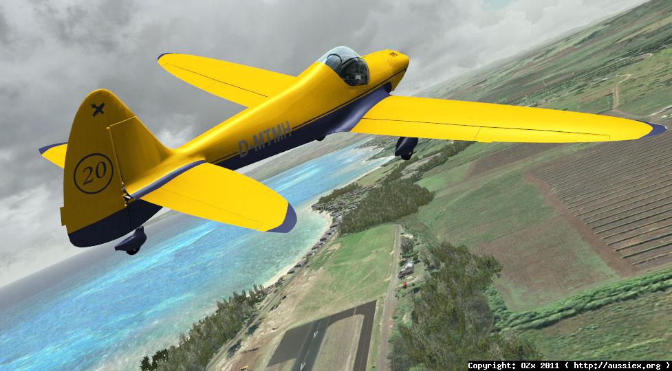
As a 3D model it is of a very high standard - as are the paint jobs offered with the release.
The world of flight simulation moves fast - there are already many repaints available to download. A few of those are shown below.
I was a bit disappointed that the release did not include the integrated tailwheel as an option - strange as they built a model of it so why not use it?
The flight characteristics seem pretty close to the real thing. However it is not so advanced as to offer a proper spin or side slip capability - which as an aerobatic mount you would expect. This is mainly a shortcoming of FSX but there are add on aircraft out there that do overcome these things.
The most annoying thing about flying this plane is that the flaps and undercarriage can only be operated when in virtual cockpit mode and only by clicking on the buttons on the panel with your mouse. I don't know about you but I always have these programmed on my joystick and every other FSX aircraft works just fine this way through the joystick. It's a real pain to have to switch modes and switch to the mouse just to put your flaps and gear up after take off. I wish they hadn't done this - it spoils an otherwise good experience.
In summary I would say that this first release of the Twister whilst offering an excellent quality 3D model and paint options has too many shortcomings to justify the price - which for us in the EU is a whopping 32 euro.
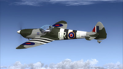


As a 3D model it is of a very high standard - as are the paint jobs offered with the release.
The world of flight simulation moves fast - there are already many repaints available to download. A few of those are shown below.
I was a bit disappointed that the release did not include the integrated tailwheel as an option - strange as they built a model of it so why not use it?
The flight characteristics seem pretty close to the real thing. However it is not so advanced as to offer a proper spin or side slip capability - which as an aerobatic mount you would expect. This is mainly a shortcoming of FSX but there are add on aircraft out there that do overcome these things.
The most annoying thing about flying this plane is that the flaps and undercarriage can only be operated when in virtual cockpit mode and only by clicking on the buttons on the panel with your mouse. I don't know about you but I always have these programmed on my joystick and every other FSX aircraft works just fine this way through the joystick. It's a real pain to have to switch modes and switch to the mouse just to put your flaps and gear up after take off. I wish they hadn't done this - it spoils an otherwise good experience.
In summary I would say that this first release of the Twister whilst offering an excellent quality 3D model and paint options has too many shortcomings to justify the price - which for us in the EU is a whopping 32 euro.



Week 13 - Fuel tanks and fitting control surfaces
Total hours to date 128.25
Didn't get anything done on the weekend as I had a cold.
Still, I did get a bit done during the weekdays.
Starting to fit the ailerons and flaps to the wings now - a tolerance of 2mm gaps is the end goal. Lots of time and checking and re-checking here.
I've superglued the aileron horns in place so will flock and reinforce those later this week.
Also the fuel tanks are prepped now and ready to go in the wing. I've been putting this off for as long as possible - a bit of a nerve wracking job when they finally go in as they will be bonded in place and once they are in that's it. No going back. So everything has to be right. Keying up the bonding surfaces is crucial so that's what I was doing last night.
They will be bonded in with PU foam - which comes out liquid and then expands on contact with air.
Will hopefully have some photos of that process next time I post.
Didn't get anything done on the weekend as I had a cold.
Still, I did get a bit done during the weekdays.
Starting to fit the ailerons and flaps to the wings now - a tolerance of 2mm gaps is the end goal. Lots of time and checking and re-checking here.
I've superglued the aileron horns in place so will flock and reinforce those later this week.
Also the fuel tanks are prepped now and ready to go in the wing. I've been putting this off for as long as possible - a bit of a nerve wracking job when they finally go in as they will be bonded in place and once they are in that's it. No going back. So everything has to be right. Keying up the bonding surfaces is crucial so that's what I was doing last night.
They will be bonded in with PU foam - which comes out liquid and then expands on contact with air.
Will hopefully have some photos of that process next time I post.
 |
| Fitting controls - starting to look like a proper wing now |
 |
| Keying the tanks prior to bonding - right one only done in this photo |
 |
| Inside of wing keyed up also |
Wednesday, 9 November 2011
Cowling design
Been doing some thinking about making an alternative cowl to the one supplied by Zulu Glasstek for the UL260i.
I find the existing cowl a little ugly (sorry Pete). Plus I think it may not be as efficient as it could be.
See the tuft flow photos below for a comparison between a traditional cowl inlet shape and a Lo Presti style round inlet design.
Not only are the traditional inlets much larger (therefore creating much more cooling drag) they have part of their opening in the turbulent (sometimes even reverse) flow which occurs near the spinner.
The Lo Presti style inlets can be up to 40% smaller as they are positioned further out in the hi pressure airstream away from the influence of the spinner. Also they are positioned further forward, closer to the prop. This makes the most of the hi pressure pulses of air coming off the prop before they become mixed with the free airstream further back.
There is a UL260 in France with this style of cowl and to me it looks a lot prettier.
I will go a different route with the oil cooler too. I plan on having a smaller inlet similar to the one on the Jabiru cowl and then a plenum which will expand and slow down the air before it meets the oil cooler. According to all the theory I have read this should result in better efficiency from the oil cooler plus a reduction in inlet size and thus a further reduction in cooling drag.
I know it is a lot of work to make your own cowl (200 hours is the average) but I think it is worth the effort in this case. We will see if I change my mind closer to when this has to be done!
Hopefully patience and persistence will prevail. (don't try saying this too fast).
I find the existing cowl a little ugly (sorry Pete). Plus I think it may not be as efficient as it could be.
See the tuft flow photos below for a comparison between a traditional cowl inlet shape and a Lo Presti style round inlet design.
Not only are the traditional inlets much larger (therefore creating much more cooling drag) they have part of their opening in the turbulent (sometimes even reverse) flow which occurs near the spinner.
The Lo Presti style inlets can be up to 40% smaller as they are positioned further out in the hi pressure airstream away from the influence of the spinner. Also they are positioned further forward, closer to the prop. This makes the most of the hi pressure pulses of air coming off the prop before they become mixed with the free airstream further back.
There is a UL260 in France with this style of cowl and to me it looks a lot prettier.
I will go a different route with the oil cooler too. I plan on having a smaller inlet similar to the one on the Jabiru cowl and then a plenum which will expand and slow down the air before it meets the oil cooler. According to all the theory I have read this should result in better efficiency from the oil cooler plus a reduction in inlet size and thus a further reduction in cooling drag.
I know it is a lot of work to make your own cowl (200 hours is the average) but I think it is worth the effort in this case. We will see if I change my mind closer to when this has to be done!
Hopefully patience and persistence will prevail. (don't try saying this too fast).
 |
| Tuft flow. |
 |
| Existing UL260 cowl design. |
 |
| Lo Presti style cowl for UL260 on DynAero in France |
 |
| How the new cowl could look. |
Monday, 7 November 2011
Week 12 - Wing reinforcement and Aileron Counterweights
Hours to date: 120.25
A decent stint of 15 hours this weekend. Makes up for doing nothing all week.
Just as well I didn't start the next part of the flap connecter job. Pete tells me it's a nightmare of a job and needs to be 0.1 of a mm correct! Also as you will see from the below photo there needs to be a bit of grinding of the connecter behind the bearing so that the pin has full travel through the bearing. As a quirk of the design the pins move relative to the connecter when the flaps are extended. This is because of the dihedral in the wings. So one pin ends up going further in and the other ends up coming out a bit. More on this job when I get to it.
Next up the Aileron counterweights. Which as you will see below need to be cut to the same angle as the edge of the aileron - something that is not mentioned in the manual (but inferred in one diagram). Pete says not to bond the weight to the panel at this stage so all I did was mix up some micro and bond them in. Micro is extremely small spheres of glass - so small that it appears as a powder to the naked eye - and is used as a lightweight filler for jobs where great strength is not required. (Flock is heavier and structural).
Bit of a fiddle to get the micro down into the aileron - which is done through the cutout for the counterweight panel - it is only about 10mm wide. The manual says use a wooden spoon - I don't have one of those so I made up a thin strip of wood and used that. The technique that worked best was to build up a mass of micro on the end of the wood and then carefully lower that down into the aileron and then once at the bottom 'wipe' the wood to one side and the micro would come off and stay put. About 5 goes of this and the area is covered in micro ready for the panel. The groove in the panel is also filled with micro and then inserted to the correct depth - leaving the weight at a certain distance out - this distance is critical as the counterweight is to prevent control flutter - a pilots worst nightmare. Worth taking some time to get this job millimetre perfect.
Next up is a even more fiddly job! Reinforcing the inside of the leading edge of the wing - to a depth of 1m. I thought I had long arms but they were nowhere long enough to get down inside there for this job (plus you are working blind if your arm is down there). So I taped a paintbrush to a long piece of wood and throughly wet out the area to be reinforced. Then dipped the 1m of tape in a cup of resin and squeezed out the excess so it was throughly wetted out before putting in place (do half of the length at a time). Using the paintbrush again I was able to position and glass tape in the right place and make sure it was wetted out and without air bubbles. Phew!
Finally at the root end a piece of carbon is used to reinforce this area. I used a new technique (for me) of clear polythene sheet to wet out the carbon cloth and avoid damaging this delicate substance (Carbon is so strong when finished but so delicate when in it's raw state). This is a great technique and avoids mess and allows for a very crisp edge to the carbon when cutting it.
The first stage is to cut out two sheets of clear polythene about 50mm larger than the final size of the job. Then mark up your required carbon size - in this case 100mm by 250mm. Cut your cloth roughly to oversize this area. Then mix up some resin and pour it directly onto the cloth. Put the polythene sheet back on top and then using a plastic card gently wipe across in several directions until the cloth is thoroughly wetted out. Then cut out to your marked line. Then you can take this to the job in hand and peel off one layer of polythene - place the cloth where it needs to be and then carefully peel off the other layer of polythene. A little very light work with your gloved fingers and you can work out any air bubbles - job done! Sorry I don't have more photos of this process but it's hard to do with resin on your gloves.
A decent stint of 15 hours this weekend. Makes up for doing nothing all week.
Just as well I didn't start the next part of the flap connecter job. Pete tells me it's a nightmare of a job and needs to be 0.1 of a mm correct! Also as you will see from the below photo there needs to be a bit of grinding of the connecter behind the bearing so that the pin has full travel through the bearing. As a quirk of the design the pins move relative to the connecter when the flaps are extended. This is because of the dihedral in the wings. So one pin ends up going further in and the other ends up coming out a bit. More on this job when I get to it.
Next up the Aileron counterweights. Which as you will see below need to be cut to the same angle as the edge of the aileron - something that is not mentioned in the manual (but inferred in one diagram). Pete says not to bond the weight to the panel at this stage so all I did was mix up some micro and bond them in. Micro is extremely small spheres of glass - so small that it appears as a powder to the naked eye - and is used as a lightweight filler for jobs where great strength is not required. (Flock is heavier and structural).
Bit of a fiddle to get the micro down into the aileron - which is done through the cutout for the counterweight panel - it is only about 10mm wide. The manual says use a wooden spoon - I don't have one of those so I made up a thin strip of wood and used that. The technique that worked best was to build up a mass of micro on the end of the wood and then carefully lower that down into the aileron and then once at the bottom 'wipe' the wood to one side and the micro would come off and stay put. About 5 goes of this and the area is covered in micro ready for the panel. The groove in the panel is also filled with micro and then inserted to the correct depth - leaving the weight at a certain distance out - this distance is critical as the counterweight is to prevent control flutter - a pilots worst nightmare. Worth taking some time to get this job millimetre perfect.
Next up is a even more fiddly job! Reinforcing the inside of the leading edge of the wing - to a depth of 1m. I thought I had long arms but they were nowhere long enough to get down inside there for this job (plus you are working blind if your arm is down there). So I taped a paintbrush to a long piece of wood and throughly wet out the area to be reinforced. Then dipped the 1m of tape in a cup of resin and squeezed out the excess so it was throughly wetted out before putting in place (do half of the length at a time). Using the paintbrush again I was able to position and glass tape in the right place and make sure it was wetted out and without air bubbles. Phew!
Finally at the root end a piece of carbon is used to reinforce this area. I used a new technique (for me) of clear polythene sheet to wet out the carbon cloth and avoid damaging this delicate substance (Carbon is so strong when finished but so delicate when in it's raw state). This is a great technique and avoids mess and allows for a very crisp edge to the carbon when cutting it.
The first stage is to cut out two sheets of clear polythene about 50mm larger than the final size of the job. Then mark up your required carbon size - in this case 100mm by 250mm. Cut your cloth roughly to oversize this area. Then mix up some resin and pour it directly onto the cloth. Put the polythene sheet back on top and then using a plastic card gently wipe across in several directions until the cloth is thoroughly wetted out. Then cut out to your marked line. Then you can take this to the job in hand and peel off one layer of polythene - place the cloth where it needs to be and then carefully peel off the other layer of polythene. A little very light work with your gloved fingers and you can work out any air bubbles - job done! Sorry I don't have more photos of this process but it's hard to do with resin on your gloves.
 |
| Grind off area of connecter where pin comes through |
 |
| Aileron counterweight panel |
 |
| Cut end to match angle of aileron edge |
 |
| Counterweight in place - excuse crappy photo |
 |
| Wing up on stand so I can get to the leading edge inner for next job. |
 |
| Tape and carbon reinforcing in place. |
 |
| Cutout polythene to oversize and mark with area needed |
 |
| After this point - pour resin onto the cloth and lower sheet back on top |
Thursday, 3 November 2011
Silence Twister in FSX released
You can buy it from here:
http://secure.simmarket.com/iris-pro-series-silence-twister.phtml
32 euros in the EU - those outside the EU will be able to buy it for 27 euros (no VAT)
I will download it tonight and give it a test fly and I will report back soon on what I think.
http://secure.simmarket.com/iris-pro-series-silence-twister.phtml
32 euros in the EU - those outside the EU will be able to buy it for 27 euros (no VAT)
I will download it tonight and give it a test fly and I will report back soon on what I think.
 |
| Adrian Hattons Fixed Gear version (UK) |
 |
| My proposed paint job. |
Tuesday, 1 November 2011
Week 11 - Flap connectors
Well the bearings are in.
As stated in the manual they do require a lot of force to go in. The freezing of the bearings and boiling water on the connectors did help.
 |
| One down, one to go. |
 |
| Rigged up in the vice with wood to take the load evenly and a socket to press home the bearing. |
 |
| Both done. Small plastic inserts in 4x bearings and one large collar reduced down to 15mm - one still to do. |
Saturday, 29 October 2011
A brilliant read

I bought this book the other day from the LAA online shop.
It had arrived when I got home at 7pm.
I casually started reading it...
...and finished it at 2am.
I think it's the first book I've ever read in one sitting.
What an adventure - flying around the world solo in a homebuilt aircraft. Manuel is one of only 6 people on the planet to have done so.
He is probably the least qualified and experienced person to do so too. A relatively low hours PPL.
He obviously writes well but it is his ability to put you in the moment of what is happening that stands out. Plus he has a neat way of talking about big issues without sounding overtly offensive when he puts across his point of view.
Friday, 28 October 2011

Subscribe to:
Posts (Atom)