Tuesday 24 December 2013

Week 123 - Wiring

Hours to date: 1222.5

I've been getting on with the wiring, doing what I can before the painting of the cockpit.

I have painted the fuse box holder - the outside can be painted later to match the cockpit but I am happy for the inside just to be grey primer.

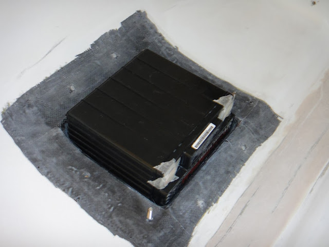
I've also fitted some brushes to the throttle/brake assembly hole so that no foreign objects can find their way down there. I just cut-down a door draft excluder that I bought from a local hardware shop. Seems to work pretty well.

As you will see below I've also decided to fit some switch guards to the outer ends of the bank of switches. They are made from stainless and will prevent any inadvertent switch throwing by a trouser leg catching on the outer switches.

The ammeter shunt and it's cover are all done. Just have to wire them up now.

An update with the wheels and brakes. After contacting the factory to clarify, the axles do indeed need an 8mm thread cutting into them. As I have the fixed gear I should have used a 6mm bolt through the gear leg, axle and brake (rather than the 8mm one I used). It's no great harm done to use the 8mm in my opinion.

As you can see the brake needs to be aligned with the gear leg - 120 degrees - then drilled through the 8mm hole (6 if you're doing it right!). Then I put a short 8mm bolt through the axle and brake and tightened that up to hold it in place while I drilled out the three 6mm holes into the brake.

I'm off on holiday for 2 weeks tomorrow (my first holiday since starting the kit) so there won't be another blog update for about 3 weeks.

I'm off to the Yucatan peninsula for some sun and snorkelling plus a trip to several Mayan ruins.

See you in the New Year.

Ammeter shunt with it's cover in place

Lining up the brake with the gear leg - 120 degrees

Clamping the brake before drilling through the 8mm hole.

Short 8mm bolt through the axle and brake before drilling out the x3 6mm holes

Brushes for the throttle/brake assembly hole

Fuse box holder all painted up with primer

Brushes flocked in place

Switch guards at either end.

Getting some wiring done ahead of time

Thursday 19 December 2013

Merry Xmas


Wiring diagram updated

Click image for a larger view

Load sheet and laziness

It's been a very lazy few weeks for me on the kit.

I've not been in the garage for 3 weekends now. A combination of being very busy at work and also feeling like I needed a break.

But I have been organizing the electrics - buying parts etc.

One of the things I've been meaning to do for a while but didnt get around to was putting together a Load sheet - for the electrics.

A guideline is to use no more than 80% of your alternators output.

As you will see below from my load sheet I am right on 80% with my total - although this is a theoretical maximum rather than a practical one.

I won't ever be using the starter while transmitting on the radio and lowering the flaps all at the same time.

Even the continuous figure I give is a theoretical Max rather than practical.

I'm also updating my main power wiring diagram and will upload that soon.


Tuesday 26 November 2013

Week 119 - Wheels and brakes

Hours to date: 1211.5


Onto the wheels and brakes now.


There seems to be some discrepancies in the manual - which has confused me a bit.


Also because I am going for the fixed gear then the section 3 - fuselage - part of the manual talks about doing one thing and then section 8 - Fixed gear - talks about another.


Neither of them seem to make perfect sense.


I've followed what Pete does with the brakes - M6, 20mm screws with Nylocks on the outside. Section 3 of the manual talks about M6 10mm screws - but these would not go through the axle flange and brake (which combined are about 11mm) let alone give enough thread for a nut and washer on the outside.

Note that I've needed to very slightly grind away a 'wedge' on the gear leg to allow the brake to sit fully against the gear leg - we are only talking about 1-2mm here - see photo below.


I've also used an M8 bolt to secure the axle and brake to the gear leg. Section 8 talks about using an M6 bolt - but then says to put an M8 nut on the end of it! So that's clearly an error. Also the stated M6 bolt (55mm) was not included in my kit.


Here's where it gets complicated...


So after fitting the brake and wheel (which is partially held on by the brake disc rotor - which must be bolted to the wheel after putting inside the brake pads) I thought I would go ahead and see how the wheel spat is fitted.


After quite a bit of head scratching it seemed to be that the ali bracket which attaches to the gear leg has 1. An M6 hole where my M8 bolt is and 2. An M8 hole where the centre of the axle is. This would indicate that I need to put an M8 bolt through into the axle - but as you will see below the axle does not have  thread on the inside.


I see on the French Twister they ended up flipping the bracket up the other way and then drilling another hole through the M6 hole in the bracket - right through the gear leg and securing it that way. Then after that they still went back and made a thread in the axle and fitted another large washer and M8 bolt through that to secure the axle.


I am hoping to be able to not have to do that.


I would like to use the existing bracket - but if it means making up a new one - then so be it.

I've also included a photo of what Pete does at the bottom - this is not in the manual - so is another of his mods. Seems to make sense though - the one M8 bolt does not seem enough to hold the axle onto the gear leg.

To be continued...


Brake from the outside

Brake from the inside - angled 120 degrees from black line.

Small wedge that needs cutting into gear leg for brake to sit flush

Wheel in place

Brake disc rotor must be put on brake first then bolted to wheel.

Wheel spat bracket

No thread inside axle...


Position of spat bracket from manual

Confusing part of the manual M6 with a M8 nut

Fuselage part of the manual
What Pete does...

Monday 18 November 2013

Week 118 - Various

Hours to date: 1200.5

Well Pete has still not made up the canopy parts I need so I've moved onto other jobs.

Kind of a blessing in disguise actually as I am now doing all the little jobs that I've not got around to previously.

The baggage tray is finished - I'm pleased with the way it turned out.

I discussed the throttle/brake assembly with Pete and he agreed it needed more than just flock to hold it in place so I'll put a couple of bolts through there. More worryingly the throttle cable in it's current position would have to go through the spar tunnel (indeed Pete says that what people end up doing - drilling a hole through the spar tunnel). Obviously I am not keen on this idea.

I see the French Twister had the assembly round the other way - so that the throttle is on the outside - this puts the cable in a better position so I will most likely follow suit here.

For such a critical component it seems to have not been thought out properly in the design stage. I'll be spending a bit of time on this as for me the throttle action (and security) must be perfect.

Another thing that Johan pointed out to me is that the throttle friction cannot be adjusted in flight - in fact the access to the friction is only through the bottom of the aircraft via an inspection panel.

For these reasons you can understand why Pete has switched to a vernier type throttle.

Another couple of jobs I did are: Reinforcing the rest of the main gear posts - I'd only done one side before as that was what the manual indicated but I noticed that the French Twister had the whole post reinforced. This doesn't add any weight really so I've done the same. The manual can also be interpreted this way to do this. The other job is making an access panel for the connection of my cowl flap - where access is very limited so it's a bit of a necessity.

I've also installed the radio and transponder antenna cables - these follow the route of the rudder cable guides. This job is great way to take all the skin off your knuckles!

I determined the position of the flap drive 'box' and have used the composite fasteners I got from Germany to put in some mounting posts for this. They are stuck on with flock and I put a single layer of glass over the top as Pete does (although the fastener manufacturer says that flock alone is enough).

Next up is the ammeter shunt - see photo below for location. I'm making a cover for this as well - the ammeter shunt carries the same charge as the terminals of the battery so it must never come into contact with anything else. Given this - it's a wonder that they don't supply a cover with them.

Finally I've installed 3 warning lights (red LEDs) into the panel. These are for 1. Starter operating (a UK CAA requirement), 2. ECU fault and 3. Low volts warning (both of which are required for the UL Power engine setup.)

Next up I will work on the main gear and wheels and brakes I think. I'm having a new spacer made up for the hub that is missing one (!) by my friend in New Zealand - Peter Boettcher - Thanks Peter!

Baggage tray all done

Carbon tabs on the side fixes it nicely in place

Throttle cable position - red line indicates current position

Front of throttle assembly - not much room before spar tunnel

Access panel for cowl flap connection

Carbon reinforcement around main gear post

Flap 'box' mounting posts

Radio and Transponder antenna cables

Ammeter shunt location

3 Red LED warning lights added to panel


Monday 4 November 2013

Week 116 - Baggage tray continued

Hours to date: 1182.5

Not a great deal of progress this week, but the baggage tray is almost done.

I put a layer of carbon over the edges where the micro was (top and bottom) - this will make it much less likely to get damaged in service, the micro is a little brittle on it's own.

Then I added 4 carbon brackets for fixing to the cell.

After these are set I will round off the corners and drill through them and the cell - before putting some fixings on the outside - the same spike-type nutplates that I used on the cell end cover.

The manual calls for a Velcro fixing of the baggage tray only. Firstly I don't know how you would do that as the tray sits horizontally on an angled cell edge - so how would that work? Secondly I don't think velcro would be enough - I prefer to have it properly secure. The thought of it coming loose during aeros and then fouling the controls below bothers me. So that's why I'm going for the carbon fixing brackets. I've also flocked a couple of small plywood blocks under the port side to support it, should the brackets ever break. On the starboard side the battery cover already acts as a 'stop'.

The seat required a little more work as you will see below the right hand side does not actually make contact with the cell floor - so I've added a heap of micro under there. I've also added some more micro to the front edges as they got damaged when I was taking the seat out the first time.

I was a little too impatient taking the seat out - with releasing a layup it is always best to use slow steady pressure. Lesson learned.

Once both the baggage tray and seat are finalised I will move onto the canopy - unfortunately Pete is taking a very long time to organise the canopy parts that I need. I'll chase him again this week.

A good fitting baggage tray - with carbon now covering the micro extended edges

Seat not touching cell on right hand side - I've put micro under there to fill the gap.

4 carbon brackets to secure the tray to the cell.


Monday 28 October 2013

Week 115 - Baggage tray

Hours to date: 1174.75

The seat is fitting really well now and with the addition of the two plywood blocks either side it doesn't move at all.

Don't worry about being able to get the seat out with them hard up against it - the seat does flex slightly so you are able to remove it after they have set.

I won't be bothering with the plywood blocks behind the seat as I have extended the cell sides (see previous post).

I've also sanded down the plywood blocks at their outside edge so they blend into the surrounding area more. I'll post of pic of these later.

As you will see below the seatbelt hole on the right hand side got obscured by the seat edge - this is a result of the cell not being square. Only thing to do here is build out with micro on the inside and Dremel back where needed.

Onto the baggage tray - as you can see I had to use a lot of micro to fill the edge gaps. This may be as a result of my battery box pushing the tray higher than is normal. I made a 'shelf' underneath on the edges of the tray out of duct tape to stop too much micro going down the sides. This worked out well.

I fitted the tray to the back of the seat using micro too.

To finish off the baggage tray I will add a layer or two of carbon to the edges (top and bottom) where the micro sticks out - to make it more durable - otherwise it will no doubt get chipped in everyday use.

After that I'll fit the tray back in and then make up some support brackets. I'll use the same fixings on the outside as I did for the cell rear cover, the ones that embed themselves into the honeycomb.

Finally there are the thigh supports - which don't really support my thighs but do provide a smooth transition from the edge of the seat and stop any foreign objects from entering the control area below the seat.

They turned out okay - I used 6 layers of glass and am keeping 3M in business with the amount of duct tape I used.

Pete fixes these to the seat but I may fit them to the cell I think - we'll see.

Plywood blocks fitted to edge of seat to stop sideways movement.

Mod to seat with micro so starboard seatbelt hole is open.

Duct tape from hell for the thigh supports layup.

Duct tape on the seatback where the tray is fitted to it with micro.

Tray in place ready for micro - note duct tape 'shelf' underneath to stop micro going down the sides too much.

Lottsa micro.

Not too much needed to fit the seat.

Baggage tray with micro - I'll layup some carbon over the micro to make it more durable and stronger.

Thigh supports - after trimming out - they fit really well and make the seat more comfortable for your legs.

Wednesday 23 October 2013

Pattern making video tutorial

Another awesome video from the boys at EasyComposites.

Part 1 of 3.

I wish I'd seen this before making the oil cooler ducts - oh well good knowledge for next time.

http://youtu.be/XeeSsmsm9h0?t=4s

They also have an excellent set of tutorials showing how to make a carbon fibre car bonnet using an existing metal bonnet as a mould.


Tuesday 15 October 2013

Week 113 - Seat continued

Hours to date: 1152.25

The seat is coming along nicely - however before I get into that I will talk briefly about the battery.

I decided it was time to order one as it is yet another thing that must be done before the cockpit can be painted.

The good news is that it fits perfectly.

Finally something going right for me!

I lined the inside of the cover and base area with special sticky backed foam which takes up any gaps and makes the battery resistant to moving around and being subject to shocks.

After that I drilled out some holes for the terminals to come through.

All pretty straight forward.

Back onto the seat...

I was only able to take the seat so far with regards to correcting the tilt of the safety cell in relation to the wing spar tunnel. This was mainly due to the left middle part of the seat contacting the safety cell (see photo below).

It is pretty good now - I used a spirit level to confirm things were square. I am only about 1 or 2 degrees out so it should be okay.

I may build up the starboard side some more - we'll see how it feels. If I do that then I'll have to put some micro underneath the seat middle on the starboard side so it contacts the cell properly.

The procedure - as described in my last post - went smoothly enough, duct tape everywhere then a heap of micro on the seat edge and where it will contact the cell on the duct tape. Use a stirring stick to clear up the edges as much as possible, then squidge the seat down with some weight on it and leave it to set.

I'm leaving it for 48 hours as I want it to be set properly hard before I sit in it.

As you will see below I am also making up some foam block (and micro) fillers for the thigh supports. When I get those right I will cover the lot in duct tape and lay glass over the seat front and onto those areas. That will likely be the subject of my next post.

These supports also act as a block to stop any foreign objects from entering the area of the lower control column.

Battery - it fits!

Terminals coming out the side

Anti-shock foam lining on the cover

Seat view from the back - you can see how much out the starboard side is

Ditto from the front - nothing I can do about this really.

Duct tape everywhere

Micro on seat and duct tape area then a heavy weight (my dusty tool box) and leave it to set.

Foam block and micro to make up moulds for the thigh supports.