Monday 19 December 2011

Week 18 - Port wing

Hours to date: 195.0

Seeing the light at the end of the tunnel now with the Port wing.

Leading edge is now reinforced.

Root rib is glassed in and I did a bit of filling in with Micro balloons in the honeycomb in this rib plus on the flap and aileron counterweights. Also at the end of the Aileron there is a gap that needs to be filled with micro. The micro tends to be like working with slightly melted chocolate so after a while it runs into a nice smooth finish. I work it into any cavities with a wooden stirring stick - usually I cut one in half to have a finer edge to work with.

I also made up a couple of plywood washers that will go in the holes in the wings for the aileron bell cranks. I used a hole saw of 30mm diameter and that makes a 26mm diameter circle of plywood when cut out. The photo shows the plywood washer with plastic (nylon?) washer on top (black) and then the ali plate that will be screwed into the bottom of the wing - this will hold the aileron bell cranks in place and allows for future removal should that be needed.

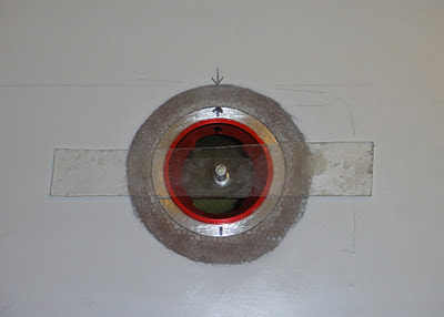
The fuel drain is now finished except for putting in the metal fittings. Managed to get it pretty flush in the end. Also the fuel cap is looking quite decent now too - with just the cavity to fill in around the edge with filler to make that flush.

Next up I will be doing all these jobs to the Starboard wing so most likely won't be posting again for a while. 

Merry Christmas everyone and see you again in the new year.

Leading edge reinforced with 40mm glass and peel ply

Root rib - Micro in honeycomb and glass on edges

Micro in the gap at the end of the ailerons

Plywood washer for bell cranks

Fuel drain pretty much done - bar the fittings

Fuel cap - looking fairly decent - just needs filler now.

Thursday 15 December 2011

Electric Twister

A very interesting article from the USA about converting the Twister to electric flight.


What's different is the authors 'Range extender' device which overcomes most of the shortcomings of electric flight. 


This makes the Twister into a hybrid which I believe is the way forward until there is a leap in battery technology.


It sure would be nice and quiet flying a Twister this way, the only real noise would be from the prop.


http://blog.cafefoundation.org/?p=2520

Merry Christmas

Santa's upgrade from the sleigh.

Monday 12 December 2011

Week 17 - More wing work

Hours to date 183.25


Cracking on with the Port wing now.


I had my inspector (Rex) round this week and he seemed pleased with my work so far.


To secure the bearings in the aileron bell cranks you need to use a centre punch which pushes out a little metal over the edge of the bearings. The distance from the edge is 1mm. I used a fine point punch first by hand to make a small dent in the right place. Then I switched to the medium size punch.


The next pic shows me just playing around with how the crank works - it will of course be on the inside of the wing when in place. I was just doing this to determine which crank goes in which wing.


Other work done this week: Fuel drain has been glassed over, flap counterweight arms are bonded in place and I have prepared the leading edge of the port wing for reinforcing - removed the peel ply, sanded down and flocked in any voids.


Finally there is a carbon washer that needs to be bonded onto the rear wing pin. The pin was put in place at the factory with their foam glue - which looks like it will be easy to remove but it is very strong and even the Dremel had a job to remove it. Got there in the end.


Just got to reinforce the root rib with glass, ditto the leading edge, then I will be close to finishing the Port wing. A few other little bits to do then I will switch back to the Starboard wing.


Centre punch around bearing to secure it.

Trying out the bell crank for function

Fuel drain glassed over

Flap counterweights bonded in

Leading edge prepped for reinforcing tape

Foam needs to be removed for CF washer on rear wing pin

Washer bonded in with Cotton Flock

Other hole cut out for the bell crank now too

Monday 5 December 2011

Week 16 - Fuel drain

Hours to date 172.25


Moving right along to the bottom of the wing now and installing the fuel tank drain.


Pretty much the same deal as the fuel filler recess. Manual doesn't tell you anything - except where to drill. Hole size is 40mm for the outside and then I went quite a bit smaller inside - 25mm and then used the Dremel to elongate the hole where needed for the two drain holes. (see pic).


This is an easier job than the filler cap because of size and also access is a lot better - you can see underneath easily and work through the hole in the root end of the fuel tank. With the filler cap a little inspection mirror is needed.


After this job I installed the bearings in the Aileron bell cranks and drilled (Dremeled) the hole for one of the bell cranks. This hole will be covered in the end by a metal plate, but is necessary for installing the crank as both bearings that it will sit in are already installed inside the wing.


I may keep going with this one wing until it is done and then switch back to the other wing - we'll see.


Inner hole made a special shape to fit the drain holes

Drain plug installed - still have to glass in.

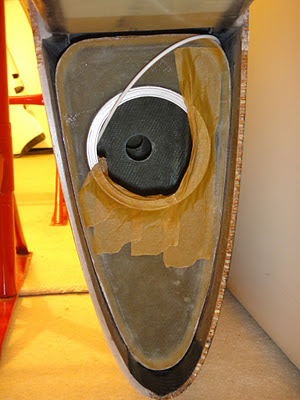
View from inside the tank

Hole for Aileron bell crank install.

Both bell cranks with bearings installed.

Wednesday 30 November 2011

Week 15 - Fuel cap install

Total hours to date 164.25


I took the plunge and bonded in the fuel filler recess.


I'm glad I didn't try to do it the other night as there was quite a bit more prep work that I needed to do first. Basically sanding areas that need to bond with the flock and making sure the honeycomb is well out of the way so the flock will fill in the void in the wing skins. I did all this by hand as I find the Dremel a bit out of control for such a delicate task.


Before starting I laid in a polythene sheet inside the tank to catch any spills of flock or anything else that might fall in there.


I then spent quite a bit of time pushing flock into the space between the tank and the inside wing skin. This is the critical junction that has to be fuel tight when complete.


After that it was putting a heap of flock in the honeycomb void and on the cap recess itself.


All seemed to go okay.


A couple of nights later I put the reinforcing glass fabric over the outside which bonds the top outside edge of the recess with the wing. I used a Rotary cutter to cut out the fabric - it works a treat. Much better than scissors - especially when going round corners. I bought mine for less than £12 on eBay - I highly recommend you get one of these. I used a roll of duct tape to mark out the outer dimension and the fuel cap turned upside down to mark the inner hole - this worked out perfect.


Just gotta wait for everything to dry now and then I'll remove the black tape that was protecting the inner anodised area of the recess. To finish the job it will need sanding to make everything flush with the wing surface - I'll have to use a bit of filler here - which I don't have at the moment - so this job will be done much later.


Polythene sheet laid inside wing to protect tank

Lotsa flock

With perspex tool in place to hold at right height


With glass reinforcing in place

Rotary cutter - get one!

Monday 28 November 2011

Week 15 - Fuel filler cap and Ailerons

Hours to date 160.5


Made some more progress with the fuel tanks this weekend.


I finally got hold of some hole saws and mandrels (the part that holds the hole saw and goes in the drill).


Unfortunately my drill only has a 10mm chuck and the larger mandrel was much bigger than this so I had to spend about 2 hours turning this down so it fitted in my chuck. As I don't have a lathe this was a slow job with a coarse file and then the Dremel to finish.


Before I drilled anything I did a 'gross error check' by turning all the lights off in the garage and shining a very bright LED lamp underneath the wing and also one inside the fuel tank from the root end and this allowed me to see where the markings were that I had made. The copper tape on the tanks shows up as an indicator very well using this method.


It is okay to be paranoid about screwing this job up as you are drilling close to the main spar and I just had to see for myself that I hadn't made a gross error as there is no going back with this job.


Using the hole saws set your drill to the slowest speed. I made a small pilot hole first of 2mm after measuring many times! (note the number of markings I made). Then a 6mm hole all the way through and only then did I use the hole saw. I couldn't get hold of a 88mm one so had to use an 86 and then carefully Dremel out the extra 2mm all round afterwards.


The first larger hole must only be drilled down through the top layer of the wing skin - as soon as you hit the honeycomb stop. (see pic).


Then change to the smaller 75mm hole saw and this time cut all the way through including into the tank itself.


Now clean out the honeycomb that is left between the smaller and larger holes.


Take care to line up the fuel cap with the airstream and mark the metal recess part up so it's bonded in the right place.


Pete has lent me a tool he made up out of perspex which helps the cap be bonded flush to the wing surface (see photo).


I got to this point and then wimped out! Decided it was the end of a long day and I would leave the bonding in till another day when I am up for it.


The rest of the day I was making up some little carbon ribs for the ends of the ailerons. These are not supplied as part of the kit and Pete had said to put a piece of styrofoam in there and then glass over but I decided to make these out of the thin carbon that was left over from all the other parts. They only weigh less than 3 grams each so shouldn't be a weight problem, plus they won't need glassing over - just flocking in the gaps and edges should do the trick.


The final photo shows the technique for fitting the control surfaces - use a piece of sandpaper down the gaps and slide it back and forth until the control surface moves freely without binding or rubbing on anything. Note the sandpaper should be used on the wing and not on the control surface as that is thin and you will soon go through it.


Hopefully in the next post I will be talking about having successfully bonded in the fuel cap.


Outer hole - stop drilling at this point

Inner hole cut right through

Lining up the fuel cap parallel to the airstream

'Scarf' 20mm round the edge for glassing to come later

Perspex tool to hold cap flush with wing

Aileron end - instructions do not say to do any more

Left over carbon from other parts

Carbon rib

Sandpaper in wing method to fit surfaces

Friday 25 November 2011

Low pass


One of my favourites from You Tube.

Cowling design - Part 2

From my previous post about the cowling you may have got the impression that I was only concerned with the inlets, as that was all I mentioned.


However the inlet to outlet ratio is crucial to get right and there is much that can be done with the outlet to improve cooling performance and efficiency.


Very few aircraft make use of the exhaust gases. If anything they tend to exit at a fairly steep angle to the airstream and make no use of the small amount of thrust that they could provide but more importantly the exhaust gases can be used to accelerate the outlet air speed. 


Cooling drag typically accounts for up to 37% of total drag so it is well worthwhile to try to reduce this while still maintaining good temperatures on the engine.


Most outlet cooling drag is caused by the outlet air having to accelerate back up to the free airstream speed and this costs energy and adds drag. By utilising the exhaust gases to accelerate this air we can make them less wasteful and improve overall performance. This is called exhaust augmentation.


Two aircraft that have done this very successfully are the Arnold AR6 (Multiple winner at Reno) and Dave Anders much modified RV-4.


Pictures of both are below.


Dave Anders makes the most of smoothing the air before it gets to the outlet with a simple duct. Piper also did this with the Comanche.


If you want to see a really smooth cooling air outlet - take a look at the radiator exit air duct on a P-51 Mustang - that is very smooth and narrows down at the exit to accelerate the airflow. Of course the P-51 was made famous as the first aircraft to achieve Zero cooling drag. (a function of the thrust that was made with the warm compressed air leaving the exit duct.) It still impresses me.


The AR6 averages more than 220kts (while turning the course at Reno) on 100hp. Look at the bump under the fuselage - that is the cowling air exit and exhaust exit all in one. It worked so well when first made that the owner had to reduce the size of the already tiny inlets to get the temps up!


It is amazing that most aircraft designers pay so much attention to smooth airflow on the outside of the aircraft but almost never pay attention to smooth airflow under the cowl.


On the Twister it will be a challenge to include these design features as space is very limited under the cowl - it was originally designed around a compact Rotary engine - and has changed over the years as various powerplants have been installed. The biggest of these is the UL260. However I believe I can still employ the Lo Presti style inlets and UL power offer a carbon plenum with round inlets as an option which will make the job somewhat easier to implement. I would still like to explore different exit ducts to improve that area as best I can in the space.


Dave Anders RV-4 exit with exhaust augmentation

Note aluminum sheet exit duct to smooth airflow

No muffler though so it must be noisy...

Arnold AR6 - bump underneath is cowl and exhaust exit

The small but perfectly formed Arnold AR6

Thursday 24 November 2011

Week 14 - Aileron hinge pin bearings, reinforcing ailerons

Total hours to date 149.0


Got both aileron hinge pin bearings bonded into the wing, plus reinforcing of the ailerons in the horn and counterweight areas.


Both fuel tanks are now bonded in and I am preparing the parts that will be fitted to them.


The fuel caps come in a lovely anodised red which must be taken off completely where they will be bonded with flock to the wing and tank. Let the Dremel be your friend here! Finish with a corse grade sandpaper to give it a good key. This will be crucial to have fuel tight tanks when done. The black tape in the photos is just to protect the anodised surface that remains after sanding.


Going to buy some hole saws this weekend so may start the cutting of holes for the fuel caps and drains if I'm in the mood.


Ailerons held in place while 5min epoxy sets hinge pin bearings in place.

Aileron horn and counterweight reinforcement with 25mm tape

Fuel caps

One 'virgin' cap and one keyed up

Black tape is to protect the inner which keeps its anodised finish

Thursday 17 November 2011

Week 13 - Fuel tank fitting

Total hours to date 130.75


Well I took the plunge and bonded in one of the tanks last night.


The job seemed to go okay.


First off I sanded down the raised solder blobs so that the tank would be as flush as possible with the inner of the wing. This should maximise the bonding surface.


Then I did a 'dry run' - installing the tank without the PU foam on it to make sure it would slide in easy and not catch on anything - just as well I did, there was a little tweaking required to make it fit easily. Actually I found once it was covered in the PU foam it slid in easier. But you don't want to find something catching when the tank is covered in PU - best to find out these things in advance.


I also did a test piece first to get a feel of the working time of the PU foam - all the info on the pack is in German and Russian so that wasn't much help. The photo below was taken after 30 mins. The blob this started with was less than 20% of the volume of what you see here - so it does expand up quite a bit. I wouldn't want to spend longer than 5 minutes before it goes in the wing as the foam starts to take on air bubbles at around the 5 to 10 min mark.


The photo of the PU on the tank was taken before I put about another 50% more PU on it - better to have too much than too little here. May as well use up all the PU in the bottle - hold it up to a very bright light to see how much you have used.


Next step is to bond in the root end edges with 40mm tape. Then the even more scary job comes next of drilling holes in the wing for the drain and fuel cap. Gotta buy a few hole saws before I do that.


Tank before covering with PUR foam

Partly covered with cris-cross pattern - I added another 50% after this

Test piece after 30 mins - expanded about 500% at this point

Tank in. Edges to be reinforced with 40mm tape.