Wednesday 28 November 2012

A gaggle of Twisters

Or a flock. Or a flight. What do you think they should be called when gathered in such numbers?

Tuesday 27 November 2012

Week 67 - Ducts and Cowl Flap

Hours to date: 665.0

I'm feeling a bit better about the ducts now - having worked on them for another week.

I was able to save the flanges and make them flat(ish) by using the Dremel followed by some trusty body filler and sanding with my Permagrit block sander.

Then I put another layer of carbon on both sides - to cover the body filler.

I'm still in the process of fitting the ducts to the oil cooler and this is a slow process - taking a bit off here and there until they sit nicely against it.

There is room for a layer of foam (door sealing type) all around which will make things air tight.

I also built up the cowl flap and am pretty pleased with the way it turned out.

I did this using 4 layers of carbon to make up the sides - then cut them out and shaped them with the Dremel and file.

I stuck the sides on with 5 minute Araldite first then used flock and 2 layers of glass to reinforce the join. It has turned out very strong and fits perfectly on the sides. I also flocked in the hinge. I won't flock in the other side of the hinge to the fuselage lower until the outlet duct is fitted.

The other little job I got done was to make some more holes in the rudder pedal adjustment bar.

Not so straightforward as I couldn't get a drill in there due to the top bar being overhead the bar with the holes in it.

Thanks to my brother Mal for figuring out the solution - a half round file makes the right shape then once a hole is formed in the middle size it out with a small round file. 

Turned out good - I have put 3 more inches of travel in the system.

This will still be 2 inches less than standard (at the short leg end) as I have moved my safety cell end forward by 5 inches to accomodate my extremely long legs.

Should be okay for all but the shortest of legs.

This week I will continue with fitting the ducts to the oil cooler and after that perhaps try my hand at making the flanges for the other ends of the ducts.

5 minute Araldite on the edges before flock and glass

Fits perfectly - well chuffed

Ditto

Flattened flanges with last layer of carbon

Early test fit - lots more fitting to do here

Filing out the new rudder pedal adjustment holes

3 new holes done - all works good.


What is left of the duct plugs...

Wednesday 21 November 2012

Twister hot dogging in FSX

http://youtu.be/SDV-byxOBCY?hd=1

Nice little video of some flight simmer hot dogging in the IRIS Twister.

I think it shows the quality of this model off pretty well.


Week 66 - Ducts Part 2

Hours to date: 652.25

What a mission these ducts are turning out to be.

But not mission impossible.

And I'm learning a bit along the way.

I figured out what I did wrong when using body filler on the foam plugs. 

I thought I would miss out the micro layer stage - as you have to wait 24 hours for the micro to get hard for sanding, and it's harder to sand than filler. 

This was my mistake. 

The micro actually etches into the foam, whereas the body filler tends to sit on the surface and so when you are sanding it can grab and tear the foam. Also I was using 40 grit sandpaper to start with, which was too coarse really.

Lesson learned is - use micro on foam - at least for that first layer to sand.

I put plenty of layers of primer on once things were smooth with the body filler - this was several stages of sanding then priming again to fill in the little inevitable pinholes that appear.

After that a final sand with very fine paper and then it was onto the cutting compound and polish stage. Followed by 3 layers of release wax (3 layers is not enough as you will see later on!)

I have read that you should use 10 layers of wax with Polyester but I was planning to use PVA release instead.

I gave that a go and it didn't work - as you can see from the below photo it beaded on the wax and didn't form a smooth layer.

I don't have any spray gear in my workshop but had been given the tip that you can apply PVA okay with a foam brush (see photo below).

Maybe I shouldn't have used any wax at all before trying the PVA - I'm still not quite sure what went wrong here.

After cleaning off the PVA I was getting impatient so decided to go for it and get on with laying this thing up. (another mistake!)

So out came the gel coat and I struggled to apply it in a smooth layer - but put it on extra thick anyway.

It sets very quickly so I didn't have much working time.

Polyester is a different animal. I felt much less in control than I do when working with Epoxy.

I also experienced Exotherm for the first time. I've read about it before, but to see it first hand was a little scary to start with.

Exotherm is the reaction of Polyester resin with it's catalyst - even a small amount gets warm after 20 minutes or so. The first batch of Gel Coat I mixed was way too much and when it turned to jelly after about 15mins I set it on the floor. After about 30 minutes I went back to it and it was disturbingly hot - I almost couldn't touch it. So I took it outside to cool off. It was also rock hard by that point.

No harm done but something to be aware of.

Also it means that you shouldn't layup more than 2 layers in one session with polyester as the heat will distort the mould/plug and shrink everything - not good.

So I ended up putting the gel coat on and then one layer of fiberglass in the first session.

I left that for 24 hours then did two further layers of fiberglass. One of the nice things about Polyester is that you don't have to key up the surface before using it - so long as you are applying it on top of existing layers.

I also put some carbon on the flanges for the nut plates that are to be attached later.

Not too pleased with how this all went - I felt for sure I had screwed the whole thing up and was not looking forward to having to start again with new plugs.

So a couple of nights ago I crept into the garage and began to see if I could salvage this job.

The 3 coats of wax did not allow for easy release of the plug from the part - although it did release in the end.

Turns out Gel Coat is pretty strong stuff and if you are careful you can use a flat blade screwdriver to slide along under the plug and gouge away at things to get the foam out. Gel coat can be cut and polished later to take any small scratches out.

It took about 2 hours to get the first plug done. I've still got to do the other plug and then think about the flanges for the other ends...

Joy!


Final check of duct plugs for position and size.


PVA mould release and foam brush

Duct plugs with 3 layers of wax on them.

PVA - not working for me.

On with the Gel Coat - I told you it was bright!

Both done but not happy...

About an hour to get to this point

One down one to go.

Inside is smooth thanks to the Gel coat. Flanges are rubbish!


Wednesday 14 November 2012

CEA 308 - Speed Machine

Just discovered this great little plane.

Built in Brazil over 10 years by students.

It recently broke Mike Arnolds long standing (20 years) Ar-5 speed record.

The weight class is under 300kg (all up weight at take off).

It is just tiny!

And fast...

360 km/h (at sea level).

Powered by a 80hp Jabiru. (Mike Arnolds AR-5 was powered by a Rotax 582 - 65hp).

Look at the size of the inlets...

And note the placement of the outlets. (In an area of low pressure - that's what I am planning to do with my cowling).

Inspiring stuff.

(Click on pics for a bigger view)


Monday 12 November 2012

Week 65 - Ducts

Hours to date: 636.25

From the below photos it looks like I haven't made much progress this last week - but it's not for lack of hours put in.

I underestimated the amount of time to get the ducts ready for paint by a factor of about 3.

Anyway finally got there at the end of yesterday.

If anything the primer now shows where I still need to do a little work.

As you can see I have the duct plugs sitting away from a block of wood - I put 3 long screws through the wood and then just pushed the ducts onto the screws - easily done through the urethane foam. It makes them much easier to handle for painting.

Hopefully I'll have these ready for laying up by next weekend.

I'm still trying to figure out exactly how to do the flanges - but no doubt they will be made oversize as I can always trim them back to fit afterwards.


Fill, sand, fill again, repeat...

First coats of Primer

Wednesday 7 November 2012

Radiator theory

I thought I would try to pass on some of what I have learnt and how it relates to what I'm doing with the Twister.

Firstly some basics.

Piston engines generate a lot of heat - approx 70% of the energy generated by a piston engine is heat. Only 30% of the energy goes to actually driving propulsion.

Some heat goes out the exhaust, some is radiated away from the engine itself - the rest must be dealt with or the engine will overheat.

So you can have an air cooled engine or a water (radiator) cooled engine.

An air cooled aero engine is actually better described as an air/oil cooled engine as the oil is a key factor in it's cooling.

If you think about it, all piston engines are air cooled, as it is the air passing over a radiator that is taking the heat away (not the fluid in the radiator itself - that is just moving the heat around).

So to keep the oil cool we need a radiator (as oil is a fluid and this is the best way to cool it).

A radiator without ducting is very inefficient and very draggy.

Only about a third of the air striking its surface actually goes through the radiator. Plus it's whole face is being projected into the airstream resulting in massive drag.

So we must have ducting to be efficient.

Ducting also allows us to put the radiator and it's plumbing out of the direct airstream and expose only it's core to the cooling air.

So where to put this radiator?

Pete has put his in front of the engine as you can see below.

He has been through about 4 variations to get to this point where his temps are okay. (He's also had to put some more exit louvres on the rear of the cowling).


So although this is a known working solution there are two things I don't like about it.

1. It's inefficient.

2. It's ugly.

Note the size of the inlet is the same size at the radiator face - therefore he is not getting any of the efficiencies that a duct brings. There is no outlet duct on his setup.

By having a trumpet shaped inlet the air inlet opening can be much smaller than the radiator face - reducing drag.

A duct shaped like a trumpet at the radiator face does two things.

1. It slows the air down - thereby allowing it more time in contact with the radiator as it passes through it - so better cooling.

2. According to Bernoulli if the velocity is reduced the pressure must increase (the opposite of what happens on the top of a wing). Therefore if the pressure goes up then this means more air molecules passing through the radiator and so better cooling. It also means that the air is more inclined to go through the radiator (to an area of lower pressure.)

See this diagram below for the ideal inlet and outlet shapes - note that the lower funnel shape is incorrect. And the outlet at the top has a nozzle at it's end. (more about that later).


As Pete has a retractable gear version there is nowhere else to put the oil cooler so I can understand why he has put it where it is.

As I have the fixed gear version I have a big empty space in the fuselage that would normally be taken up by the main gear.

Not only that, this location is further back on the airframe - anything further back on the airframe suffers less drag as the air has already been disturbed before it has got there. (A generalisation).

Also under the wing there is an area of high pressure - just what we need for an inlet.


Not only that - this high pressure moves rearward when the angle of attack is increased - such as when in a climb attitude. (see above diagram).

This puts the air where we need it when we need it most - in the climb.

For the air inlet scoop I was influenced by the P-51 Mustang.


Notice the position on the airframe - under the wing and down away from the boundary layer. Plus the opening is angled rearwards so that maximum air enters in a high angle of attack - such as in the climb.

For the exit I have positioned the outlet as far back as I can where the wing has an upward slope. I am hoping that this provides a suction type effect as well as a very smooth exit of the airflow back to the surrounding airstream (this is the ideal situation).

Just recently I found this diagram of the De Havilland Mosquito radiator. The radiators are positioned in the leading edges of the wings.

Note the exit - which is what I am doing - although I'm sure the designers would have liked to exit it further back but the main spar of the wing prevented this.

Note also the cowl flap which does two things.

1. Controls the exit volume.

2. When open it makes a 'lip' that generates low pressure behind it - effectively sucking the air out.

I will also have a cowl flap and I expect to have to use it in the open position on the ground and whilst in the climb or doing aerobatics. When on a reduced power setting at a higher speed in the cruise I hope to be able to close it completely.


Now I know you're thinking - how about some modern designs that have moved on from WWII? Well, believe it or not things never really progressed after WWII as the jet age took over and all the best designers worked on jets after that so very little research and development in this area was done post WWII.

The exit design is the crucial bit to recover the energy losses from the drag caused by the inlet and the air's passage though the radiator itself. Most people don't realise how important the exit is.

In 1935 an Englishman called F. W. Meredith (working at RAE Farnborough) wrote a paper on this and ever since it has been known as the Meredith Effect.

Basically the idea is to heat up, then speed up the airflow as much as possible to, in effect, create a little thrust (a bit like a mini jet engine).

I don't expect to get much (if any) Meredith effect from my set up as the Twister does not fly fast enough. Generally anything over 300mph and the Meredith effect becomes a big deal. The Spitfire was the first aircraft to utilise the effect and it counted in a big way towards it's top speed.

However the Spitfire designers/developers never made the most of the effect as the ducts were too short. The Mustang made full effect of it and reduced it's cooling drag from 400lb to 50lb (negative thrust) - giving it a great top speed and helping it have a tremendous range.

Note the net outcome of the Meredith Effect is not thrust but drag reduction.

The principle remains the same though - speed up and direct the exit air to as close to the free airstream as possible to minimise losses.

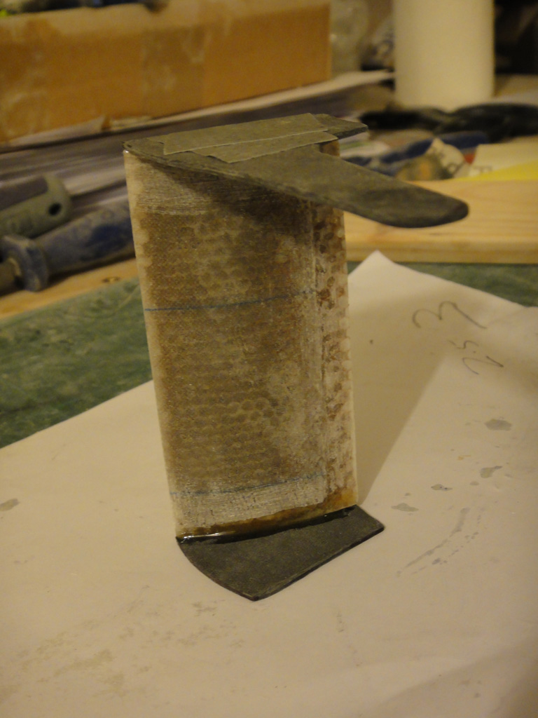
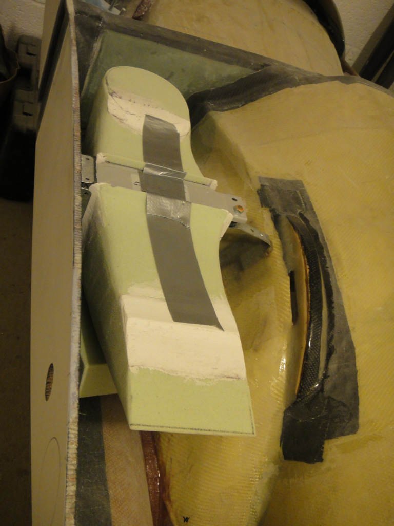
Below is my set up in the Twister.


As you can see the theory is all there - however as always with these things the proof will be in the test flying - we will see...

Monday 5 November 2012

Week 64 - Oil Cooler part 2

Hours to date: 621.75

It seems I spoke too soon when saying that I was faster with carving the ducts. Sure the initial shape was quick enough but I have spent at least as long again refining the shape to get it perfect.

This is mainly due to the ducts having to 'fit in' with everything else - whereas the scoop was the first step in the process and so a bit more freestyle.

I think I've got the outlet duct how I want it now. The inlet duct still needs a little more work. When that is done I will cover them both in body filler and sand smooth before painting with a primer.

I cut out the exit outlet in the lower fuse - then sanded down the edge to get it as smooth to the airflow as possible. I then filled in all the exposed honeycomb with flock.

You can see from the below photos how I cut out the cowl flap from the same area. It is also sanded down to an aerodynamic shape. Still got to add the side parts to this, a hinge and then of course figure out how it all gets connected to a control lever in the cockpit.

The hose fittings for the cooler finally arrived, so I fitted those and used the Dremel to carve out a space for the inboard fitting. As you can see it doesn't come too far into the cockpit - about 10mm or so.

To make the bulge inside the cockpit to accomodate this I will duct tape the fitting then use plasticine to make a little smooth cavity over that. Finally I will flock over the whole lot and extend that over the edges to make a smooth bulge. Finishing with a layer or two of Kevlar.

The Plasticine is to allow for a little gap so I can put some heat reflecting silver material in there. The oil should run at about 80 to 90 degrees so I don't want that heat coming into the cockpit.

I've bought a big sheet of this heat reflecting silver fabric and will cover anywhere the hoses come into contact with the fuselage.

I finished off the scoop as well - putting a layer of fabric on the inside and covering the whole thing in micro and body filler then sanding until silky smooth - ready for paint now.

Once all this is finished I think I'm going to move onto the rudder pedal installation - but that is a few weeks away yet as I want to finish this oil cooler install completely before moving onto another job.

If I get the time this week I may do a post about Radiator theory and how that theory relates to what I'm doing here. I've certainly learnt alot about them while working on this project.


Tight fit with the cooler - just enough room for a flange at the top (bottom)

Cowl flap and exit hole cut

Cowl flap in closed position

Oil cooler with hose fittings and cell mod

Fitting comes through about 10mm into cockpit

Ducts on cooler for position check

Ditto


With fuselage lower in place

Ditto