Saturday 24 December 2016

Flight testing

We've been very fortunate to get some gin clear days this December so quite a bit of the flight testing has now been done.

The LAA minimum is 5 hours of flight (including one 2 hour flight) and 15 take offs and landings before completing the test schedule paperwork and applying for a full permit.

G-FUUN has done 4.6 hours and 14 take offs and landings to date. So one more flight may be enough to complete the testing.

Chris has done 3 flights and 1.6 hours. I've done 3 flights and 3 hours.

On the last flight I 'bashed the circuit' and did 8 take offs and landings. 

I have to say that G-FUUN is a very well behaved girl, it's the easiest handling taildragger I've flown.

The undercarriage does not have any dampening so tends to bounce you back up into the air a little bit if you touch down with any kind of vertical component.

Once the tailwheel is on the ground it tracks straight. I've been 3 pointing it and this seems to be the best way - certainly before tackling a big crosswind that is. I will probably revert to a 'wheeler' landing when the time comes to fly it in a strong crosswind.

On Chris's advice (and example) I've also not been getting the tail up too high on take off (as I was doing when high speed taxiing). Just let the tailwheel get about 20cm off the ground (once you have rudder authority) and let it fly itself off in that attitude when it's ready.

All has not been straight forward though - on my second flight after performing a long climb of approx 6 minutes (as part of the testing schedule),  I noticed when leveling off that the Voltage had dropped down from it's normal 14.5 to 11.8. I immediately headed straight back to the airfield at high altitude. After 10 minutes it dropped to 11.7 volts and so I joined the circuit and got back on the ground. 

I didn't fancy my second ever landing being a dead stick one.

As you may already know the UL Power is an 'electric' engine. That is, it needs an electric supply to run both the ignition and fuel pump. As the Alternator was not charging the battery then the plane was running off the battery only. It's only good for approx 40 minutes in this condition before the voltage drops below 10 on the battery and the engine will stop.

So I grounded the plane until I found out what the problem was.

After checking the Dynon was not giving spurious readings by wiring up my Multimeter to the battery directly and running the engine - sure enough the Dynon was correct and the voltage was dropping slowly as the engine ran.

Off came the cowlings and it didn't take long to see what the problem was. See pics below. The Molex connector that connects the wires from the Alternator to the Rectifier/Regulator had melted (due to that long climb and being too close to an oil hose connector - which had got up to 95 degrees C +).

So I've cut out this Molex connector completely and just used butt splice connectors and routed these wires up and away from any heat source.

Once that was fixed and ground tested we were back in business.

Chris flew the complete aerobatic schedule - as part of the testing - on Tuesday.

He gave it another glowing report and finished up by saying "You've got a Rolls Royce aircraft here!".

He also said it was much more slippery than Pete's Twisters - it accelerated quicker and retained its energy better - all good news for aeros.

Pete has challenged me to a 'race' next year to see once and for all if a fixed gear is quicker than the retractable. It will be interesting to see what happens in that side by side test. 

The only issue from the aerobatic schedule was fuel venting out the vent line on the downline of the stall turn - see video below. Chris is not used to this happening so I will need to contact Pete to see what's going on and if there is a fix for this.

Video of the aero schedule here: https://youtu.be/fweoCIosUuY

It is recommended to watch this on a laptop or desktop as the annotations do not show up on mobile or iPad. 

G-FUUN is now up the back of the hanger and put to bed for January as I am away in New Zealand and Asia and won't be back until February.

So this blog will be a little quiet until mid February.

I intend to continue posting information as and when it arises and if I think it's worth sharing although it won't be the regular weekly or fortnightly updates that you are used to.

Happy New Year to everyone and here's to a FUUN filled 2017!


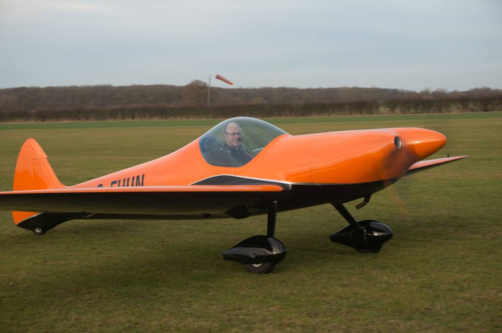
Sky reflections on my 2 hour flight

Chris inverted as part of the aerobatic schedule

Chris just about to set off on the Aerobatic Schedule flight. (I used to fly the Piper in the background.)

High speed fly by from Chris.

Landing

Making the most of this good December weather.

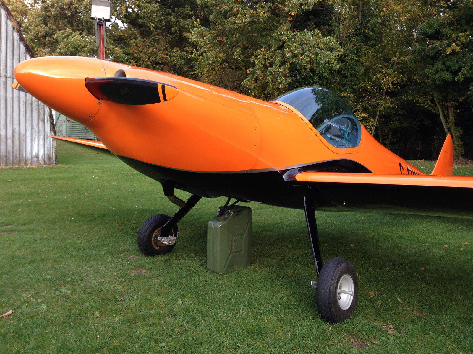
I've gone the 'Adrian Hatton route' of attaching the gear leg fairings to the fuselage with self tappers and then taping up the gap and fittings and then just leaving the bottom edge free to move on the gear leg. (Only good if you're not rigging and de-rigging all the time).
P-clip to secure the wing pins - nice to know they won't come loose whilst performing aeros.

The melted Molex connector.

Ditto. The offending article has now been removed from the system.

Wires now connected with butt splices and re-routed up and away to avoid any heat effects.

Max RPM. 149 knots straight and level (cowl flap closed). Note: throttle is not WOT at this speed - it is retarded to about 85%. Ignore the EFIS it has not had it's zero pitch set yet.

High speed cruise with cowl flap closed. 130 knots.

Cowl flap open and a bit less revs - maybe even in a very slight climb here. 125 knots.

Figures from straight and level. Note two sets of figures for cowl flap open and closed. Oil temp goes up by 5-10 degrees with it closed. 2650 is a sweet rev setting for the engine.

Climb performance. Not sparkling but to be expected as it is G-FAAT after all.


G-Meter after Chris' aeros schedule. +4.3 and minus 1.9. It's had a proper work out!

Tuesday 13 December 2016

Sunday 11 December 2016

First flight(s)

Today was the first flight(s) of G-FUUN.

I'm happy to report all went very well.

Chris did 2 flights then I did one. Each flight was about 20 mins.

Chris said that it flies hands off - no trim adjustment needed. I concur.

All the T's and P's are green in flight.

I think it will be okay to close the cowl flap in the cruise as the oil was 80 C with it open. We left it open today but maybe I will try it out on the next flight and see how it goes.

Cruises at 125 knots at 2,800 rpm. Pete Wells' Twisters only get between 110-115 knots at this rpm.

On the first flight Pete arrived in the circuit by coincidence so he formatted on Chris. See pic below.

First impressions are it feels very solid and stable in the air. Not like a light aircraft at all. The rudder is very sensitive in flight though - Chris says it is normal. Something I'll have to get used to. Excellent forward visibility in the cruise and quieter and less vibration than the Pipistrel Virus SW I've been flying lately.

I'm still smiling...

My thanks must go to Matthias and Thomas Strieker for creating such a wonderful machine - it really flies like a dream.

Also thank you to Peter Wells for all his support, patience, knowledge sharing and generosity over these last 5+ years.

And thank you to my family for supporting and encouraging me and listening to me when I had a tale of woe about yet another set back to tell.

A better video is coming soon but in the meantime here is the first take off:

https://youtu.be/KvtZSJjkGL8
1st take off

Chris on the first flight with Pete in formation

Grinning like an idiot after my first flight

Friday 2 December 2016

Getting close to that first flight

It's been a good week.

Firstly I dropped off the silencer and pipe to our local guru welder Chris Baglin of Merlin Engineering.

Chris turned the job around in 2 days flat and only charged me £50 which I thought was very reasonable. The work was of an extremely high standard too.

While that welding was being done I took the opportunity to make up some new deflectors for the front cylinders. The previous version - Mark 2 - still did not bring the temps close enough, with a difference of between 10 and 15 degrees from the front to the back (the back being hotter).

So Mark 3 deflectors were made up - these cover almost the entire front half of the front cylinders. I overdid it a bit and now the temps are too hot at the front! But the difference now is only 10 degrees, so I will cut down the deflectors a little bit and hopefully they will be close to 5 degrees difference, which is what I've been aiming for all along.

A chat with my test pilot Chris Burkett revealed that Pete's Twisters have up to 20 degrees difference between cylinders. This can't be all that good for them.

So today with everything back together I did some more high speed taxi's.

See the video by clicking on the link below.

https://youtu.be/PiEsoSg89Cc

All would be ready for a first flight on Sunday (and the weather looks good too) but Rex my inspector has gone to France this week and won't be back till next Friday so we've lost another week. Oh well it gives me time to thoroughly test this new weld and make sure the exhaust is not cracking again. Murphy's law says that next weekend will be crap weather.

Also I've now been approved by the LAA to help Chris with the test flying. Chris will still be the lead pilot and do the initial flights plus the aerobatic schedule but I should be able to take over after that if there are no other issues.

Mark 3 deflectors - a bit too much as it turns out. Not riveted or RTV'ed here yet.

Beautiful welding from Chris Baglin of Merlin Engineering.

CHT's just after shutdown. Some more tweaks to the deflectors needed.

High Speed Taxiing. (the Video link is in the above text.)

Friday 25 November 2016

Another set back

All was going so well...

I'd made the electrical changes that the LAA were asking for and then did some more ground running and high speed taxiing, up to 40 knots with the tail up. The Twister seems easy to manage on the ground and this was despite a significant crosswind.

All good. Until I went to clean the mud off afterwards and while cleaning noticed that the exhaust pipe seemed loose.

Sure enough it had cracked completely around the outside of the weld.

So it's cowlings off and all to bits again to get this fixed.

I am using a local guy who is guru. Does welding for Shuttleworth Collection aircraft and is CAA approved. He also repairs and rebuilds old Formula 1 cars.

I think he will be able to come up with a solution for a fix.

As always with these things I see a silver lining. At least it happened on the ground and not on the first flight which would have been bad. Also it gives me an opportunity to slightly change the angle of the pipe to clear it's fairing on the cowl as it was a bit close before (no heat damage to date but it's nice to know it will be 5mm further away in the future).


Thursday 17 November 2016

Well, well, well...

...what have we here?

A Permit to Test?

Surely not?

But before you get too excited dear readers - there are still a few hoops that I need to jump through before flying can begin.

There are a few small changes to my electrical system that the LAA requested. 

Namely:

1. Use a separate fuse and power wire (and both contacts on the switch) for the backup fuel pump. (I already had this initially then at the last minute when wiring up decided to change it to make it simpler, an error on my part as it then became a single source of failure for a backup device).

2. The ability to switch off power to the Main bus (and therefore the Avionics bus at the same time) without switching off the battery (The UL Power engine needs the battery connected when it is running). This function is only for switching off power in the event of an electrical fire.

So I'm working through these changes and finishing off a few other little jobs at the moment.

If the weather gods shine upon us we may see a first flight within 2 weeks.


Friday 28 October 2016

Problem solved - and a new hat for me

As I write this I am indeed enjoying a cold beer although I'm not sure I deserve it.

Before taking out the feed line in the tank I decided to check that it was not the return line that was causing the problem as this was recommended as a test by Patrick at UL Power.

So I removed the -8 line from yesterday and reattached the old feed line but kept the return line out into a measuring jug to check the flow.

I was so surprised to see that the fuel pressure was now correct and the flow rate normal.

So it was not the feed line that was the problem but the return line.

As there is only a bulkhead fitting on the return line into the tank then surely this could not be the problem for the high pressure? 

Sure enough it was not but on checking the JiffyTite quick connector I felt it was not connected correctly - these connectors are not so great as they are a bit of a pain to fit securely and especially so when the wing is on and I am trying to reach my hand up into the tiny space where it is to connect it.

After a bit of wrestling with it - I finally managed to connect it properly - using both hands - one hand through the gear leg top opening and one hand through the central access panel which is a bit of a reach.

After that a simple check of running the fuel pump and the pressure was normal!

What is that they say about always looking for the simplest solution to a problem first?????

Anyway I have a new hat to wear now while I drink my beer.

(BTW I have connected up the wing several times and each time I must have not connected up the return line correctly so that shows that the connectors are a bit flawed in their design, allowing some flow, but restricted when not fully connected. They should only allow full flow or no flow at all - bad design!)


Thursday 27 October 2016

For every problem there is a solution.

At least that's what I keep telling myself.

This blog started with a Kennedy quote about doing things not because they were easy but because they are hard so I can't say to myself I didn't say so earlier.

Although that feeling when you've solved a problem is great and one of the 'treasures' of the human experience.

Let's start with some good news!

The fuel leak from the Starboard tank has been fixed - yay!

It was indeed coming from the drain/vent area. My fix was pretty simple, just fill that area up with 'neat' resin. 'Filling the bath' so to speak.

I put some fillet wax (yellow stuff) over the top of the drain so it didn't jam up with resin - this worked a treat.

Then I just used our tried and trusted method of a little syringe to squirt the resin into the offending area.

Onto the engine rough running problem...

By a slow process of elimination I am getting closer to the solution.

I've been in direct contact with the UL Factory - specifically Patrick Denorme - who is the technical guru there. He has been helpful to bounce ideas off and generally steer me in the right direction to find the problem.

The 'some sort of flow restriction' comment he made to me all those weeks ago at the Sywell Rally has proven to be correct! (so far).

I suspected the brass end of the Vans flop tube could be the culprit as it has a smallish hole in the end - although it does have several other holes around the side - see pic below.

So the first test I did was to remove the brass end and weigh down the end of the hose with a big socket - held on with some safety wire.

No change whatsoever. Same symptoms as before and same high fuel pressure - 53.4 psi all the time.

OK...

I suspected it may be my 'feed' fuel lines that were the culprit - being that they are only -6 size which is internal diameter of 9.35mm. The UL Power installation manual is a bit contradictory as in one part it says the opening from the fuel tank must be a minimum of 8mm and then in another part it says that you should use 12mm internal diameter hoses for the feed part of the fuel lines.

So what is it? 8mm or 12mm? If that doesn't sound like a big difference then imagine the flow rate through a 8mm hose which has a surface area of 50mm squared compared to a 12mm hose which has a surface area of 113mm squared, so more than double.

As I have -6 hose then the surface area is 68mm squared.

However Patrick has said the hoses are fine at -6.

Just to be sure yesterday I took off the -6 hoses and ran a -8 hose (internal diameter of 11.2mm) all the way to the pre-filters from a Jerry Can.

Another engine run and guess what?

It ran sweet again, with identical fuel pressures to the -6 hose from Jerry can test.

OK - so we know that the -6 hoses are okay from the pre-filters to the wing root quick disconnects and we know the quick disconnects are OK too as that's what I used to test from a Jerry Can.

Once again I must point out that the UL Power manual is a little wrong in that it states that 'normal' fuel pressure is 43.5psi but this is only at warm up type revs - say 1200 to 1500 rpm. Once you run up to max static the fuel pressure goes up to approx 49-50 psi. Patrick has said this is perfectly correct to have these higher pressures at max static power settings. The manual needs to be clearer here I think.

Going back to my old tests I was able to confirm that when running from a Jerry Can from the wing root connectors and using -6 hoses the fuel pressures were IDENTICAL at all rpms to the test with -8 hoses. This confirms that the feed hose size is not the issue.

This is quite a weight off my mind as I did think I may have to replace all my feed lines with -8 hose. This would mean replacing the Andair fuel selector, quick disconnects, flop tubes and all the fittings = EXPENSIVE and PAININTHEASS.

So the problem definitely lies in the area from after the quick disconnects to the start of the flop tube.

As you may remember there is a tortuous path that the fuel must take through many 90 degree corners in my set up - see pic below. So tomorrow I will remove the complex fittings and lines inside the tank and just attach a piece of hose and test run again. BTW this is Pete Wells set up, -6 hoses and a simple piece of hose laid into the tank as a flop tube.

It's no good saying fingers crossed this will work as I just have to keep working through all the permutations until the problem is solved.

After the -8 hose run I did another run with the top cowling removed - Johan in Belgium has been asking me to do this for weeks - and I'm glad I did as two interesting developments presented themselves.

1. I got a higher static RPM. Max static was now 2,600 rpm. I also noted a higher idle too, that was approx 100 rpm higher than with the cowling top in place.

Patrick puts this down to the engine receiving cold fresh air through the air filter, although this brings me nicely onto point 2.

2. I noticed in the latest installation manual edition - only published about 1 month ago - that there is now a section on the ECU that describes a small brass fitting on it which should be connected by a hose to an area that is close to the inlet/air filter. This hose gives the ECU atmospheric data so it can give the engine the best mixture. This information was not in the old manual (published in 2013) which I used when installing the engine last year. Unhelpful or what!

Once again I find the Installation manual contradictory here as in another section it states "The injection system is pressure and temperature compensated...". OK so why does it need that hose to the ECU??

Patrick does not give me a straight answer to this but says:

Inside the ECU there is a pressure sensor to measure atmospheric pressure. Starting from this pressure, ECU change the mixture . So this is an altitude compensation. However, it is necessary to measure the airpressure close to the inlet air filter. If the ECU is close to the engine and the pressure on this brass connector is the same as near the inlet filter, there is no need to install a hose. However, if ECU is inside the cockpit, or if you use an inlet airbox, it is necessary to install a hose from the nipple to the inlet air filter.

As you have a 100 rpm difference, it means that maybe you create an underpressure under the cowling ( because engine suck a lot of air ). So I propose to install an “inlet airbox” Kit K060001 ( or K060002). This an alu box with the airfilter integrated) to be fixed on the left or right side cowling.

From the box , an 50 mm hose go to the throttle body. Make hole in the cowling and install a naca to bring air inside. In this case, you have to install a hose from brass nipple ECU to the inlet air filter inside the box.

Cut up my brand new shiny cowling!!!!!!! Ehh not just yet I won't. I will try installing the hose from the ECU brass fitting to be close by to the air filter first and see if that gives an improvement.

Ultimately of course he is right that cold fresh air will give more power - in this case it is approx 4hp more - but this is new information from UL Power. They already have hundreds of engines running without a NACA inlet and airbox.  And the old installation manual makes no mention of this.

I have also heard that this is a 'quick fix' for too high CHT temps as the colder inlet air cools the cylinders from 'the inside out' as it were.

Maybe this is something I will do later on as a mod but I can report that Pete Wells has already done this and didn't notice any change in the power output from it. (See my post from June 17th for pics of Pete's set up).

Another thing I found in the new manual is the recommended size of the oil cooler has changed. It used to be 13 rows and it's now 16 rows. I'm very lucky that I opted to err on the side of caution and go for 16 rows - I made this decision many years ago now and I'm glad I did.


As soon as I get to the bottom of this flow restriction there will be a very cold beer with my name on it.


Fuel pressure from wing tanks - too high at 53.4psi

Ditto - it is even too high before engine start as shown here.


Warmup from Jerry can with -8 hoses. Note fuel pressure.

Max Static rpm from Jerry can with -8 hoses.


Higher idle with Top Cowling removed.

Higher static rpm with Top Cowling removed. Another 100 rpm and approx 4hp.

My fuel lines from the wing root to flop tube - somewhere in here there is a problem.

New info about the brass connector on the ECU. Would have been nice to know this a year ago! Also the "silent blocs" (rubber mounts to you and me) are a new addition - I did this already in my installation. This also allows a bit of air to flow around the case which is no bad thing.

-8 hose in place for engine test bypassing all the -6 feed lines. No change!

Engine test with the top cowl removed. 100rpm and approx 4hp more achieved.

Fuel drain area prior to neat resin filing up this 'bath'. Leak is now fixed.

Friday 21 October 2016

Electric Twister - more photos

Can you tell I love this thing?


I see they have opted for the Adrian Hatton style of securing the gear leg fairings to the fuse rather than the gear leg. Also note the NACA inlet on the underside - no doubt for cooling of some component.

Woodcomp prop. 146 knots cruise!

The motor is tiny! It weighs just 13kg but puts out 100KW (approx 134hp). A big battery pack up front to control the weight and balance plus batteries in the wings too.

A very spartan cockpit.

Monday 3 October 2016

Videos of Electric Twister

What a sweet machine.

WANT!

Nice HD video here with no sound:

https://youtu.be/2f9iovtnRwU


And this one with a short write up and some sound. 

http://www.aeronewstv.com/en/industry/general-aviation/3549-silence-twister-the-first-swiss-electric-aerobatic-aircraft.html


2 steps forward, 3 steps back

Where to start?

As the engine was running sweet using fuel from the Jerry can then I assumed it would run sweet from the wing tanks now that they were cleaned.

How wrong!

A second lot of ground running from the wing tanks gave exactly the same symptoms as before, 'catching' when I changed throttle settings and generally not sweet, smooth running.

This was using the master fuel pump rather than the backup pump - which we know is damaged in some way. In fact when I did try the backup pump this time it died completely.

I've been filming the Dynon so I can analyse the readings later on at leisure.

Compare the readings below to see the difference - the fuel pressure is different in the second lot of running which would indicate a flow restriction in the wing tank to fuel quick disconnects at the wing root. From the first test we know that the flow is good from the wing root to engine and back as it ran sweet from the Jerry can.

Funnily enough the tank pickup to wing root is the only area of fuel line that I did not flush out so perhaps the restriction lies in the flop tube pickup - which does have smallish holes in the brass end.

Despite the apparent sweet running from the Jerry can you can see that the fuel pressure is still slightly above normal - which should be 43.5 psi according to the UL Power manual. It's 49 psi from the Jerry Can and 53.4 psi from the wing tank. Max permitted is 55 psi.

The fuel lines I am using are above the minimum diameter required so I'm not sure why the pressure is so high.

Anyway we will get to the bottom of this problem eventually but now onto the other problems!

I tried to calibrate the fuel sender but moving the min level dial had no effect to the gauge. After reading the instructions again I remembered that I shortened the fuel probe - which is okay to do - but you must re calibrate the sender when you do so. This can be done with a Multimeter which I rigged up but again it did not work. A further investigation with the Multimeter revealed that the sender wire (which should only have a reading of 100mV or less) was reading 11.7 volts so there is a mistake I've made with the wiring somewhere along the line that is pushing battery voltage levels through the sender.

Something to investigate when I take the instrument panel off, which I have to do anyway as I have to wire up the Red Cube to the Dynon for fuel flow info.

Another problem was with the gear leg fairings which sit at the top of the gear legs and fair in the leg to fuselage junction and cover the hole there. As you already know these do not fit the fuselage very well at all and are tight on the gear legs. I stupidly fitted them with the fuselage upside down and with no weight on the legs, so the holes I have tapped into the legs for the attachment of the securing bolts are never going to line up now that the gear has the weight of the aircraft on it.

I was thinking of doing what Adrian Hatton did and securing the flat plate area of the fairing to the fuselage and then leave the bit further down un-fastened so that this becomes the area that moves when the gear flexes but Pete Wells warned against this saying that I need to use the factory method as the gear leg flexes so much that it will crack the fairing. 

So I've put flock into the old holes and will redrill and tap out new threads for the securing bolts soon.

And now the final problem - we always save the best (worst) for last!

After the second lot of ground running I returned to the airfield to find yet another fuel leak from the Starboard wing tank. This is not coming from the same area as before as I pro sealed the inside and outside of the securing bolt this time and this area was dry - no leaks.

The leak is coming from the tank somewhere. quite low down as I found when I was draining it and monitoring if the leak was still coming out or not. 

If I'm lucky I think it will be coming from the hole made for the fuel drain and tank vent. This is the logical first port of call as there was a hole made in the tank for these items to be fitted and if there is the tinniest of gaps in the flock then a small leak would happen. It is indeed a very small leak as the speed of the fuel coming out was very very slow

Anyway so that dripped out all over the fuselage bottom and stripped the paint off again just like the other side (the previous leak happened on the Port side).

So now we have matching shittyness underneath on the black paint. No problem here as the fuse base has to be repainted anyway in it's entirety. This just proves that the wing root area and fuselage base were not painted correctly all over.

Hopefully I will have a more positive post next time round.

Trying to calibrate the fuel sender - I had to jury-rig up these wires to connect up the sender to the power source and give access to the dial on the sender at the same time.

1st ground run from Jerry Can after sustained full power run and back to warm up revs - fuel psi is okay here.

1st ground run from Jerry Can at Max Static RPM. Good that the oil temp stabilises at this figure but bad that the fuel pressure is so high at 49 psi. Still running sweet at this though.

2nd ground run from Wing Tanks this time. Note the higher fuel pressure. 53.4 psi now. This is from the start of the run so the CHTs and EGT's are lower.