Monday, 23 November 2015

Week 224 - Cowling Part 3

Hours to date: 2115.75

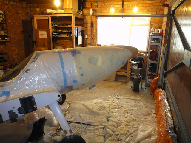
After 20 odd hours of filling and sanding I decided it was time to try a coat of primer to see just how imperfect things were.

Still quite a bit more work to do of course but things are looking not too bad on the top and upper sides plus the lower front half.

I've used nearly a whole 4kg tin of filler (and sanded most of it off again) to get to this stage.

After 'flatting off' the primer it's easy to see the low and high points that need attention. I've also bought some guide coat paint which is black and will use that next I think as it shows where low points are even clearer than the grey primer does.

Just got to keep plugging away at the plug till it's perfect. :)

Grey stuff is body filler. White is micro underneath.

Time for a coat of primer.

I've painted the spinner too so it's easier to visualise the whole thing together.


After flatting off the primer and filling mistakes - looks like a man that's cut himself shaving.

Monday, 9 November 2015

Week 222 - Cowling Part 2

Hours to date: 2096.0

I seem to be making good progress with the cowl. 

Although the early stages give big gains in a short space of time the further into this we go the smaller the gains. The basic shape comes quite quickly then making that shape 'perfect' for the mold takes a lot longer.

That 'making it perfect' stage is where I am at now and will be for some weeks to come.

I ended up using all my 2 part foam, about 6kg in total. It expands up to 25 times in size. It kicks off quickly with an exotherm and gets hard enough to work in about 30 minutes.

To carve the foam I used a rasp, and in places where access was limited - in between the inlets and spinner for instance - I used 40 grit sandpaper.

As you can see the foam did not go perfectly so there were a few cavities that needed further foam to fill them.

After shaping for about 5 hours I switched to Micro and put a thin layer of that over the foam to seal any holes and give a smooth(ish) hard surface.

I've done two layers of micro at this stage and have now switched to body filler as it is much quicker to work with.

To start with I wasn't in love with the cowling shape - particularly at the bottom where it looked a bit 'fat'. But after covering with micro and sanding that down it seemed to grow on me. I am happy with the front though - it looks quite sleek and low drag looking.

The next few weeks will be spent getting the plug to perfection as any flaws will be transferred to the mold and subsequently the part and we don't want that.

Getting the basic shape sorted in foam - this stage goes quite quickly

Some cavities need filling with more foam.

Looking sleek at the front

First layer of micro on.

After sanding the micro. Liking the look of the shape even more now.

Cowl will be a bit asymmetric due to the staggering of the cylinders.

Bit of a 'fat bottom' but i think this will visually disappear when it is painted black.


Monday, 2 November 2015

Week 221 - Cowling

Hours to date: 2078.5

The carbon brackets worked out good and are plenty strong enough.

I've put them in place and they will be good indicators for the foam carving to see where to stop.

I'll let the photos do the rest of the talking here.

Carbon brackets that will hold the cowl out at the back.

Brackets in place.

Ditto

Cardboard lined with a bin bag so the foam doesn't stick to it.

Final - double layer of protection for the engine before pouring foam.

All ready to go.

Eek - what a mess.

Frankentwister - I've created a monster!

2 hours later - we are starting to see a shape we like here.
 

Tuesday, 27 October 2015

Another elipse in the skies


From France comes another elliptical wing design light aircraft.

Find out more at: http://www.vh2streamline.com/

I am also pleased to see the outlets for the cowling being on the side!

They are claiming a 145 knot cruise (@75%) with a Rotax 912.


Monday, 26 October 2015

Control surface deflections

Something worth noting - when I state a control deflection then it for the UK only and does not correspond with the official Twister Flight Manual. See below.

Only the elevators are the same.

And in the building manual the flap deflection is different to the flight manual.

Maybe the flight manual needs updating?


UK LAA data above, Flight Manual below.
From the building manual - flap deflection does not match up with the Flight Manual.

Week 220 - Throttle cover, Spats and Cowl

Hours to date : 2064.25

The wheel spats are virtually finished now - lots of hours put into these but the fit is now spot on around the gear leg.

The throttle cover is finished now too - just needs painting. It fits very nicely.

It must be time to start on the cowling!

First things first - I have made up some molds for brackets which will hold the cowling clear of the fuselage at the rear - by 25mm at the bottom and lower sides then gradually blending into the fuselage further up.

This results in quite a large exit volume with little drag penalty - as I hope to not have a lip on the exit. I'm also making use of the low pressure area on the sides of the fuselage to help the air leave the cowl easier. Something the Sea Fury and most other late model air-cooled fighters of WWII did.

If you look at the inlet and exits for the Sea Fury it is hard to believe they were enough to provide good cooling for 2,500 hp - a masterclass in cowling design I'd say. The designers also made use of the high speed flow out of the exhausts to suck the low pressure air from the cowl.

Having taken measurements of Pete's cowling inlets and exits I am happy to report that my inlets will be just over half the size of Pete's. With the outlets I am about two thirds of his volume - and without that drag inducing lip (and louvres) he uses.

Pete's inlets total 42,900mm squared, mine total 22,200mm squared.

Pete's outlets total 65,600mm squared, mine total 49,600mm squared with the oil cooler cowl flap open and 44,875mm squared with it closed.

As always the proof will be in the testing but with my sealed plenum then straight away we are talking about a 50% increase in efficiency. With the oil cooler I hope that there will be a further drag reducing element as well as an increase in efficiency with the ducts and sealing. The front of the cowling should also prove less draggy, particularly in the lower front cowl area (where Pete has his oil cooler).

Another principle of good cowling design is to have as little surface area as possible - and certainly no flat plate area's within 150mm behind the prop. Something my design allows me to do.

To allow for any changes to the design I will make a removable piece around the exhaust area which can be easily changed should my design not prove to work perfectly first time round.

So bear with me dear readers as the next few months will just be about the cowling - I hope it proves an interesting exercise - even though most of you will never need the information (you're much too sensible to build your own cowling!).

First stage is to protect the engine before pouring expanding foam around it, so that's where I'm up to this week.

Hopefully I'll be ready to pour foam next weekend and get carving.

Fitting spats to the gear legs - filling gaps with flock.

Making the mold for the throttle cover - wood is to hold the foam against the fuse side.

Spats fitting pretty nicely now.

Throttle cover all done - bar painting. I used 4 layers of glass for this, it weighs just 36 grams.

Covering the engine - putting foam around all the sharp bits first.

Foam is to stop the plastic covering from piercing on any sharp bits.

Making up the cowling brackets - these are 10mm deep for the upper transitioning section

Ditto - these are 25mm - for the rest of the cowl. Using 7 layers of carbon here.

Bye bye engine. See you in a few months.

Hawker Sea Fury cowl. Not much exit volume for 2,500hp.


Sunday, 11 October 2015

Week 217 - Throttle, Wheel Spats and First Engine run

Hours to date: 2032.75

So happy to report that I was able to start the engine for the first time! See video at the bottom.

Longer video of the second run here: https://youtu.be/bclv6NybbnE

More about that later - but first the wheel spats and throttle.

I've finished fitting the anchor nuts to the brackets (M6) and the spats (M4) and also body filled the edges around the brake protrusion mod and the edges of the cover where they don't quite lie flush with the spat. Overall it is a good fit although there will be quite a bit of fitting to do with the Starboard spat to the gear leg as it does not fit nearly as nicely as the Port one does.

I've fitted the throttle and it works really nicely - especially from an ergonomic point of view - much more comfortable for my long arms in the cockpit.

The bracket holding it in place in the cockpit has been over engineered - it's like a brick outhouse. Although I am happy to say it will never fail. This being a primary control I like to make sure it is structurally very sound.

I even used a P-clip on the end of the outer structure in the cockpit to take any strain away from the main fixing, not that it really needs it.

Just got to paint all that and make up a cover for it now.

At the engine end I've made up a 6 layers of carbon bracket which holds the throttle control in place and keeps it clear of the engine.

Onto the engine run.

All went well and as you will see from the video it fires up after a very short crank on the starter.

I warmed it up at slightly higher revs than is usual as this was the first start and we don't want to glaze the bores. So I warmed it up at 1,500rpm rather than the usual 1,200rpm.

Oil pressure is within the green arc, All EGTs are very similar except one which is about 12 degrees different - not sure why at this stage. CHT's were similar till I did a higher power run - up to 2,300rpm where the front two stayed at 90 degrees and the back two went up to 100 degrees. I think this is mainly due to their not being any cowling in place so there is no pressure difference going on to help stabilise the CHTs. Hopefully they will be more even when we have the cowl in place.

With the Oil temp - it took a long time to come up - so I ended up ripping off the cardboard wedge I'd made and taped in front of the oil cooler exit to produce a low pressure for the outlet. The highest the temp got to was 70 degrees. Normal operating should be between 80 and 100. So it looks like my oil cooler is working too well at the moment. Again hopefully these things will settle down once all the cowling and fuse bottom panel are in place. BTW having a oil temp that is too low is a good problem to have and easier to fix than one that is too high.

The idle is about 20rpm too high at the moment so will need a little tweak.

Need to finish off the spats and sort out a few other little things then I think I will be moving onto the building of the cowling.


Glassing over the brake protrusion holes and making up a carbon bracket for the throttle.

Throttle in place. Note P-clip to help take the strain.

Throttle with carbon bracket in place.

Ditto.

P-clip on the bracket to hold the throttle control in place.

Trying out the anchor nuts on the spats

Inside view of the spat

After body filling and sanding.

Ditto.


Friday, 2 October 2015

Week 216 - Throttle and Wheel Spats

Hours to date: 2010.75

A much more positive 2 weeks this time.

I found and fixed the ECU fuse blowing fault. It was my error in connecting one of the sensor wires to earth.

I received a new fuel pump, fitted and tested that. All is now working well and with no leaks. You really have to do up the copper washers quite tight for them to seal effectively.

I've made a start on the throttle - it's going to end up looking exactly like Pete's set up - so I take back what I said about Pete's setup looking too complicated!

At the engine end is a rose jointed rod end - with a threaded inside which will be connected to the throttle. A spacer is required to put this joint away from conflicting with the throttle arm as it moves. I made the spacer out of some Ali tube I had lying about.

On the inside of the cockpit I have begun to think about where the throttle will go. From an ergonomic point of view - redoing the throttle - has been a bit of a blessing in disguise as previously my elbow was hitting the back of the cockpit when I pulled the lever to idle - in fact I had to bend my wrist slightly to get the throttle to full idle which was not comfortable. With this new set up I should have free movement and in a better range for my arm as it will be further forward.

There have been a couple of other fixes for this problem. The French Twister used a (to me) very complicated and unproven modification which increased the effective travel of the throttle at the engine end. I am against this type of thing on principle - especially for such a critical component as the throttle. In the USA Deb Van Treuren has been able to fix her throttle by just cutting out the slot in the cockpit to increase the travel of the lever - which is a good solution if the ergonomics permit it - unfortunately for me they don't so that's why I'm going for the Vernier set up.

Onto the wheel spats.

Fairly straightforward job this - but as always on the Twister - an added complication!

I'm guessing the brake set up has changed since the molds were made for the wheel spats as the small cover does not fix on because of confliction from brake parts protruding - see photos below. 

Also I found that the Ali bracket that fixes the wheel spat on seems to be out of position - too much bracket at the front and too little at the back. Again I see that the French Twister had this same issue. I have gone for a similar fix to the problem by creating an add on bracket at the back to extend the bracket so it lies underneath the wheel spat.

The M6 dome head screws will be fixed on by the use of nut plates riveted to the back of this bracket set up. Instead of the normal 2 I will have 3. And despite the instructions saying to use self tapping screws in the rest of the cover I will go for M4 dome head screws into nut plates - a more long term solution than self tappers which tend to wear holes and pull out of fiberglass over time.

The throttle itself has arrived in the post so I will get going on installing that over the next week or two. Hopefully then we will be ready to attempt another engine run.

New throttle - engine end

Ditto

Carbon bracket to attach throttle in cockpit - just rough positioning with plasticine here.

Initial positioning. Tailplane should be horizontal to measure distance from back of wheel spat to the ground - 220mm - not shown correctly here as I was just starting the job.

Hole made to clear brake protrusions filled with plasticine shaped for later glassing.

Back is protected with cardboard - to stop plasticine from pushing through.

Spat in place with bracket mod.

Ditto with spat removed.

You can see the brake protrusions here.

Ditto - they don't stick out by much but they do stick out - hence the mod needed.