Sunday, 21 April 2013

Week 88 - Fuse box/Lower panel cover and 2nd Aileron shroud

Hours to date: 895.25

This week I got the shelf into the fuse box/lower panel shroud.

I waited until the fuse box was delivered as I wasn't exactly sure what height I wanted the shelf at - better to wait than work blind.

As you will see below the fuse box also acts as a main bus and a remote ground (for non noise-susceptible items).

This will mean a lot less little wires in the loom going up to the main grounding point on the firewall.

I also fitted some nut plates to the shroud, these will be how the lower panel is attached to it.

The shroud is then bolted to the cell floor with a rubber mount and then two more bolts at the rear (I've yet to fit those).

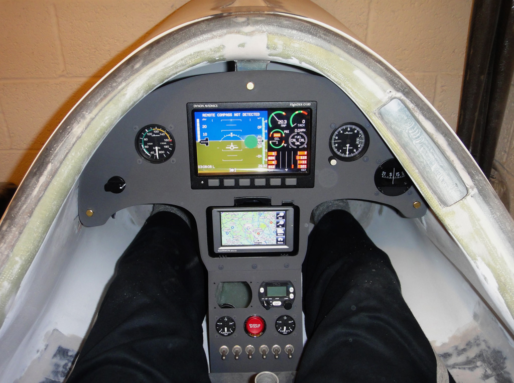
The other little job I've done is to make a mounting tray for the remote compass (this talks to the Dynon).

It has to be mounted well away from everything else - so is going in the rear of the fuselage.

I've just put some micro on the screws to encapsulate them. After that is set I will mount in the fuse with flock on the lower edges.

The remote compass has to be exactly (within 1 degree) the same pitch and yaw as the Dynon in the panel. I will use my protractor spirit level to do this. (a left over tool from my last plane, I used to use it to adjust the pitch on the propellor).

Onto the second of the aileron control rod shrouds.

A bit of a dogs dinner here...

Just look at how different the cell is on that side to the other.

The cell is also a different shape on that side too. I've no idea why though.

A much bigger (longer) hole is needed. I noticed Pete's were not even either - one was 125mm and the other was 185mm. This means that the cell is not bonded in square with the fuselage. You can see this in the photos below.

All of this is hidden when the seat is in place so only I will know it as an eye sore!

Next week I will hopefully fit the Lower panel shroud to the cell and also fit the remote compass.

Trying the shelf and fuse box out for position

2nd shroud in place - note completely different holes...

Fuse box in place

Ditto

Nut plates and rubber mount for fixing to cell

Remote compass mounting tray - micro-ing in the screws.

2nd shroud flocked in place.

You can see the cell is cock-eyed in relation to the fuse... Twisted!

Monday, 15 April 2013

Week 87 - Panel, aileron control rod shroud

Hours to date: 886.25

Made some fairly good progress this week.

I got one of the aileron shrouds fitted.

I paid a visit to my wings in storage to measure where the holes were cut in the root ribs - just to make sure I was cutting the hole for the shroud in the same location.

Just as well I checked - mine was 5mm different to Petes.

The most important thing is to get the middle of the shroud in the middle of the aileron actuator. Mine turned out to be 72mm from the spar tunnel.

Lots of stopping a checking with this job. And then just nibbling away at the edges until everything was a nice tight fit.

Once the ends are filed or Dremeled down flush, both ends are flocked in place (on the inside).

Onto the panel...

I couldn't think of a good reason not to install all the instruments.

So I went ahead and did that.

Looking pretty good now. The only thing missing is the radio - which still has not been delivered. More about that saga when it reaches it's conclusion!

I powered up the Dynon too - the only reason I could do that is because I fitted the back up battery - which is an option. Around £100 I seem to remember just for a battery!

As you can see from the back view - I put a dab of torque seal on all the instrument threads.

Next steps will be getting the shelf into the fuse box/shroud and then fitting that to the lower panel and cell.

First hole cut and centre line for inside hole marked.

Outside end made flush

Inside edge before trimming flush with Dremel.

Inside all done - still got to body fill the edge gaps to make it flush

Flocked in place.

Pre cutting to shape - note NOT a straight line - the cell is curved.

Panel in.

Powered up Dynon.

Dynon and GPS powered up - radio (and placards) still to come.

Back - showing torque seal on threads


Thursday, 11 April 2013

Week 86 - Fuse Box/Lower Instrument Shroud

Hours to date 874.75

This past week I've been building a shroud/box that goes behind the lower instrument panel.

This has 3 functions.

1. Protect the lower instruments from damage (by pilots feet getting in and out).

2. As an attachment point for securing the lower panel to the safety cell.

3. The space in the back section will be used for a fuse box.

Pete has a similar shroud - although he does not use it for his fuses. He mainly uses circuit breakers and any fuses are on his side panels.

As I don't have side panels and won't be using circuit breakers (read the Aero Electric Connection to see why) then I still need a place that will be easily accessible on the ground for the fuses.

I started off by making a mould out of cardboard - which I covered with duct tape as a release.

I used 4 layers of glass and there is quite a bit of overlap on the edges and corners.

The black line on the final photo shows where I will install a 'shelf'. This will be where the fuse box is mounted.

I will most likely also make a cover for the top at some point.

The notch in the bottom part is for a rubber mount that will go through the safety cell and attach to the lower of the panel also - making the whole unit secure. There will also be a couple of bolts at the back to secure the box.

I've made both Aileron shrouds now - still trying to release the second one from the mold! Nightmare...

So I guess the next job will be to install those.


Making the cardboard mould

Mould made and covered with duct tape

Laying up - and the other aileron shroud in the background

Black line indicates where shelf will go for fuse box

Tuesday, 2 April 2013

Week 85 - Panel, parts building and Control column

Hours to date 863.5

I decided against the satin black for the panel. I did paint it that colour but it just did not look right. So I took Pete up on his offer to paint it with his fancy glider panel paint. £90 for a small tin!

It comes out with a texture almost like sandpaper, so no light is reflected off it. I went for the charcoal colour as that will match the rest of the cockpit interior.

Pete's 3rd Twister has still not taken it's first flight. The LAA required him to load test the bomb - and it passed with flying colours (no pun intended)

I helped him mount the motor and install a few accessories. A good learning experience for me.

I finished up the tailwheel bearing shroud. I just used a round file to shape the bottom part to fit over the cross member.

Fits good and should protect that bearing from all the muck off the tailwheel and it weighs nothing.

Onto my part making...

Pete was kind enough to lend me his moulds for the aileron pushrod shrouds and the wing pin retaining clips. These clips are an aftermarket mod by Pete - and I have to say I do like the idea of the wing pins being secure!

I used 6 layers of glass for the clips - which may have been a layer too much as they are a bit stiff - but they should still flex enough to get the pin in.

The aileron shroud is just 2 or 3 layers of glass laid up over a foam plug (with parcel tape to release). Dimensions are 430mm long by 95 high with a width of 70mm at the root end and 30mm at the control column end.

Actually I am finding it a real hassle to get the shroud to release from the plug - as I don't have compressed air in my garage so I can't use that - which is the normal trick. A blast of that down the sides and most things release.

I think I will use release wax as well for the next shroud to make things easier.

Onto the control column.

Part of knowing where to cut the holes for the aileron shrouds is having the control column in place first.

It's a fairly straight forward job to build up the control column.

I used my new heat gun to heat up the metal before putting the bearing in and it was so effective I really only needed the lightest of taps with a hammer and socket to drive it in.

Getting the bigger bearing onto the flange was also easy.

What became more of a mission was getting the other big bearing onto the part that the flange sits on (and the control stick itself is attached to at the other end).

Maybe due to the anodising that Pete had done on this part it was slightly thicker? Anyway the best thing is to get hold of a 24mm deep socket. I just had a normal one and used vice grips and an adjustable spanner underneath it to extend it's reach as the bearing was moved down.

The flange is then driven onto that other bearing and a locking washer is bolted in place with a locking pin as added security to hold it together.

I found that it was rotating perfectly until after hammering in the locking pin - this had the effect of tightening the play on the bearing and made it catch a bit. 

The secret is to only do up the bolt on the end to finger tight and then after hammering in the pin you may have to pull the pin out slightly with a pair of pliers to get the bearing to rotate freely again.

Drilling out the coach bolts was a bit focusing! As you are drilling through the spar tunnel.

Nothing is mentioned in the manual about where these holes should be drilled. Luckily I measured Pete's twister while I was there and noted the gap at the base of the aileron actuator - which is only about 8-10mm. The distance down from the top of the spar tunnel to the top of the mount flange is 40mm.

As you can see below this puts the coach bolt at the very base of the spar tunnel inside the cockpit. A little Dremel work is required to make it fit nicely. I also used a small square file to shape out the hole for the square end on the coach bolt.

Fits very well now with no play. The lower bolt is easy by comparison.


Tailwheel carbon shroud in place


Foam plug for aileron shroud with parcel tape

Aileron shroud and wing pin clips lay up

Panel with Nextel glider paint

Finish is like sandpaper

Aileron actuator before fitting bearings


Bearings in and stick mount fitted

New toy - heat gun

All together

Locking washer on the back - holds bolt and pin in place

First bolt in

Control column in place


Pete's 3rd Twister
Pete painting my panel
Wing pin clips and moulds - made from ali

Tuesday, 26 March 2013

SWIP Twister Promo video

Great vid of the Twister Duo in action.

http://youtu.be/XXVrXLQ4y1w


Nose Art

Decided to explore some ideas for Nose Art.

Behold the Tangerine Dream...

(not that I'm that into redheads but it seemed appropriate...)


Wednesday, 20 March 2013

Week 83 - Panel part 3

Hours to date: 846.5

I didn't get as much done as I wanted this week due to a cold slowing me down.

Still - the top panel has been filled and sanded and is masked off - so ready to paint.

The Bottom section is also ready - I fitted the starter button and the switch holes are now drilled.

There are 4 critical switches that should not be bumped off in flight (unless you want to do some gliding that is). They are the Master, ECU, Ignition 1 and Ignition 2.

Actually the engine will still run perfectly well on one of the two ignitions. Indeed that is how you check they are both working in your pre-take off checks - by switching one off at a time.

So I'm placing these 4 switches in the middle of the bank of 6.

The two outboard switches will be for Avionics Master and the other one will be a spare (it may be used for a landing/taxiing light - but that's something I plan to add later on once everything is up and flying and working well).

The other little job I have been doing is making up a shroud for the tailwheel fork bearing.

As you can see from the below photo of Matthias Strieker's Twister the bearing is not protected from all the dirt and grime flicked up by the tailwheel.

I noticed that the French agents Twister had a nice little mod to cure this.

A beautifully made (CNC or lathe?) piece of aluminium that sits on the tailwheel fork cross bar and supports the bearings as well as keeping them clean.

As I don't have a lathe I decided to make a shroud out of Carbon fibre.

I was lucky to find an old piece of PVC pipe to use as a mould - which was exactly the diameter I was looking for - 42mm.

I just wrapped a couple of layers of duct tape around that to act as a release and to make the diameter 43-44mm so the bearing has a little space around it for play (and grease).

I've still to file out the half round holes that will allow it to sit on the fork - I will fill in the gaps at the bottom with RTV.

Hopefully by the next post I will actually have the panel painted.

Starter button in place


Mechanical fuel gauge in place - 1 each side

Switches in place
Standard tailwheel fork bearing - exposed to dirt from Tailwheel
Tailwheel Fork shroud - made from Carbon

French agent mod - CNC or Lathe made ali shroud/support


Tuesday, 12 March 2013

Week 82 - Panel part 2

Hours to date: 836.0

Finally got the top section of the panel done.

It is now ready for paint. Although I will wait until the bottom section is done before painting.

I spent many many hours working on the GPS mount - which as stated in my previous post is 'off piste'. I've hidden almost all of that ugly plastic behind the panel - with gaps only for the release mechanism and the power button.

I'm pretty pleased with the result.

I've also made the fixings on the side that hold it in place invisible. I can't see me taking the mount out anytime soon. It would be a little bit of hassle to remove but still do-able.

The hole for the flap switch is also done. I've decided to mount it 90 degrees clockwise to the normal position as I think this is a much more logical position for it. It therefore now operates from horizontal (flaps up) to straight down (flaps down), mimicking the physical position of the flaps themselves.

Onto the bottom panel.

I spent ages cutting out the holes for the Transponder and Radio.

They are quite fiddly - and even though I started with a template it took many hours of filing to get them just right.

Unlike the ASI, ALT and Compass holes which are relatively easy - as you just use a 57mm hole saw for those.

I hope to have the bottom panel done this week and then paint it on the weekend. Then it will be a case of fitting all the instruments.

After that I think I may switch back to getting the interior of the cockpit finished - aileron pushrod holes (and covers) need to be made and the seat needs fitting.

Once everything airframe wise is done I can switch back to wiring everything up.

GPS mount in place

Bottom panel section (transponder in Radio hole just to see how it fits)

Compass trial fitting

Tuesday, 5 March 2013

Great resource - A guide to everything

The FAA bible for aircraft.

Or in their words:


Acceptable Methods, Techniques, and Practices - Aircraft Inspection and Repair.


I came across this while researching the electrics but it has a wealth of other information in there.

Free to download.


http://www.faa.gov/regulations_policies/advisory_circulars/index.cfm/go/document.information/documentid/99861


Monday, 4 March 2013

Week 81 - Panel

Hours to date: 824.0

Slowly making progress on the panel.

As you will see below I did decide to follow Pete's idea of separating the panel into two sections.

I've also angled the lower section some more (17 degrees) - so all the instrument screens are perpendicular (from the pilots point of view).

To make the flange I used the same methods I've used before. Duct tape on the upper part so it releases, then stirring sticks on each side held on with Bondo to hold the panel at the right angle while the whole thing sets.

I used 8 layers of glass for the flange - which may be a bit overkill - but it has to support the upper panel at the bottom and also I had to rivet 3 anchor nuts to it - so it had to be quite substantial.

As you can see below I've cut out the holes for the EFIS (and installed it's mounting tray), ASI, ALT and Compass holes are done too.

The EFIS must be mounted as close to horizontal (wings level) as possible as there is no way to correct it (you can correct pitch). The same goes for Yaw so I spent a lot of time with spirit levels getting things just perfect before cutting the EFIS hole out.

I'm still working on the GPS mount and hole.

The GPS mount I bought is an Air Gizmos type and allows you to remove the GPS easily (I will want to do this as I use it in my car too).

The Air Gizmos mount is a bit ugly though and normally mounts with quite a bit of plastic in front of the panel.

I've decided to mount it behind the panel and so make it much more hidden - with only the GPS and the release handle visible. Should be a much neater look when it's done.

More about that and the lower panel section in the next post.

Making the panel flange - setting angle with stirring sticks

Duct tape on the top to release it

Here you can see the lower panel angle

Trial fit of the ASI

Making progress on the top panel.